Difference between revisions of "IMFD Map"
(typos) |
(Added category.) |
||
| (3 intermediate revisions by the same user not shown) | |||
| Line 268: | Line 268: | ||
|style="text-align:right" width="33%" |[[IMFD_Course|IMFD Course Programs]] | |style="text-align:right" width="33%" |[[IMFD_Course|IMFD Course Programs]] | ||
|} | |} | ||
| + | |||
| + | [[Category: Articles|IMFD Manual 04]] | ||
| + | [[Category: Tutorials|IMFD Manual 04]] | ||
| + | [[Category: IMFD Manual|IMFD Manual 04]] | ||
Latest revision as of 11:40, 14 October 2022
| IMFD Configuration Page | IMFD Manual Contents | IMFD Course Programs |
Map Program[edit]
The Map Program is a general display used for monitoring the ship‘s course and predicting an approach to target planets. It allows the user to view entire solar system as well a single target. The map program uses planet to planet calculated trajectories. The trajectory is no longer limited to ellipses and hyperbolas now; it can be displayed over multiple references regardless the distance or influence the reference causes. The user has the ability to control the speed and accuracy of the trajectory engine. The modifications can be made from the configuration page. All modes will provide a great accuracy for interplanetary missions. Update rates as high as over ten times per second can be achieved without a significant system load with an average home computer.
The Core[edit]
The core uses the Encke-Fehlberg methods which allow a high speed trajectory prediction. In this version of the trajectory engine the graphical steps and the numerical integration steps go side by side. So, increasing a step size will lower the graphics quality. It would be possible to use a high order integration method with a long time step to compute the trajectory, and use sub-integrations to increase the graphics quality. That would be more complicated and it would not significantly increase the overall performance. So, a lower order method with a lower step size has been chosen as a default option. However, the user can select the integration method from Third order RK3, RK4-Gill, Symplectic 4th Order and RK-Fehlberg methods. Also the Adams-Multton method is under consideration. Of course, it is possible to create a much faster trajectory predictor but it is questionable that it does not provide a satisfying reward vs. effort ration. Surely, in the integrations where graphical plotting is not required, such methods could be used more easily.
Core Configuration
Some of the core functions are configured through the IMFD.cfg file. The LegSize option will define the size factor for the leg. A higher number will make the legs longer; therefore, the amount of legs required to compute the trajectory will decrease. The LegsPerFrame option will define how many legs are computed within every frame. If the frame rate is 80 frames per second and 20 legs are calculated in every frame, that makes 1600 legs per second. The integrator option will define the integration method to be used in a prediction.
Centering the display
You can center the display around a desired celestial body by pressing [Cnt] button. Then, you can type the name of the object you wish to center. The display will move to center on the object‘s current position. If you wish the center the display in a future position it can be done but only for positions and times of periapis passages. You can center the reference planet of the periapis by writing ―r-‖ in a front of the name,such as ―r-Mars‖, or the command ―p-planetname‖, which will center the display on the point (in the future) of your closest passage around that planet. Centering a particular periapsis will automatically bring up the text description for that periapsis (normally you would have to use the [SEL] button to scroll through periapsises to find the one that you want).
About the Periapis
There can be multiple periapses on a trajectory. The number of available periapses and the currently selected periapis are shown in the top-left corner such as ―Pe 1 of 2‖. ―Ref Moon‖ is indicating that the Moon is the reference of this periapis. Only the selected periapis is shown on the display. Also there are two different kinds of periapis points, strong and weak ones. This simply means that the strong periapises are located inside the SOI (Sphere of influence). The weak periapises are located outside the SOI and most likely there isn‘t a stable orbit in that position. So, that could be considered to be the position where the ship will by pass the planet at minimum range. The strong or weak periapsis will be displayed for reference and target planets only. If the trajectory goes several orbit periods around the reference planet up to six periapsises/apoapsises can be displayed, but only if ‖One Pe/Ref‖ option is disabled from the configuration page.
The Display Screen
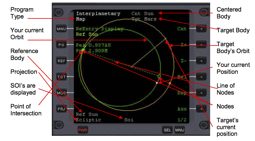
The projected course of the spacecraft will appear in bright green by default, and will appear in purple when using flight planning mode. The flight planning mode will generate a hypothetical trajectory based on the information created by some other program. The bright white dot is the spacecraft itself. The green/purple dot on a trajectory is the periapsis, the closest position to some object. The orange circle is the target orbit. Sometimes the target is not visible on the screen. The boxes on a trajectory line are the nodes. The line of nodes (dotted line) will be drawn between the nodes and the reference planet. That is the position where ship‘s orbital plane and target orbit intersects. This is also the position for a plane change maneuver. Due to the numerical computations, the calculations may cause some weird effects on the node positions. Usually they are located at opposite sides of the reference planet. The information on the screen is displayed for the periapis positions, NOT for the current position of the ship. The one exception is when no single periapis is available, and the current position of the ship is used.
Included Plane Change
The Map program will automatically include the plane change at the first node if the (PlC) is activated. Warning: Sometimes the plane change is required in a prediction but it may cause failures in a prediction if used in wrong place. You don‘t NEED the Map Program for a plane change. You can do it with only the course program.
What is included in Map
All planets included in computations have the following characteristics: a mass greater than 1e20 kilograms (this number can be altered via the configuration page in the Map Program—hit [MOD] until it comes up) and they must orbit the same reference planet as the ship, or orbit the Sun. In addition, any planet, ship or station that is selected as a reference or a target is also included. Moons that have a different reference than the spacecraft are not included in trajectory calculations.
Trajectory Limiters
Due the nature of a numerically computed trajectory, the generation of the trajectory must be limited somehow, as there is no end point in a trajectory (if nothing is done, your spacecraft will continue forever unless it collides with a moon or planet). There are two automatic limiters for the trajectory called Period and Hyperbolic limiters. These limiters will cut the trajectory—otherwise there would be too much of your trajectory on the screen and the display would look chaotic. You can configure these limiters in the map program configuration page. The period limiter will limit the trajectory to one orbital period around the reference object. The hyperbolic limiter will limit the trajectory to one hyperbolic periapsis relative to reference planet. These automatic limiters can be overridden manually by setting the time limit, which limits the trajectory in a specified amount of seconds. That is the most stable if the others fail. So, if the trajectory looks a little strange or short it may have been limited incorrectly by automatic and you should make some adjustments to the configurations.
Special orbits
You can also target a special orbit such as an ecliptic orbit, an equatorial orbit, or a geostationary orbit (GEO). The purpose of the ecliptic and equatorial orbits are for relative inclination. IMFD calculates relative inclination with respect to a target. If you want to have a relative inclination of 30 degrees to the planet‘s or moon‘s equator, set the target to equatorial so when you set relative inclination to 30 degrees, IMFD interprets this as being inclined 30 degrees to the equatorial (target you just set). Thus, an equatorial orbit has a relative inclination of zero with respect to the equator, and an ecliptic orbit has a relative inclination of zero with respect to the ecliptic. Also, the orbital plane of the reference planet can be targeted. This is good especially when transferring between planets or returning from the Moon. Special orbits can be used with all programs. Type the corresponding letter when asking the name of the target—g for geostationary, l (lowercase L) for equatorial, e for ecliptic, and r for the orbital plane of the reference planet or moon.
Flight Planning mode
This mode allows you to use the numerical multibody predictor to generate the hypothetical transfer orbit based on the information generated by other programs. When this mode is activated the ―Plan‖ text and the name of the program generating the plan will appear in a title. Also, the trajectory will be displayed in purple (in a default configuration, of course). Whenever the burn information is present a hypothetical trajectory can be generated. This mode is especially great when planning free-return trajectories and returning from the Moon.
Projections
You can select the projection plane by pressing [Prj] button. Because the space is three dimensional, displaying it in a two dimensional display will cause some graphical problems. Therefore, choose the proper projection. Options are Self (your orbit), Ecliptic (ecliptic of the reference planet), target (the target‘s orbit is used as the projection), periapsis, and HTO (your hypothetical orbit).
Nonspherical Gravity
The Map program includes non-spherical gravity in its predictions. Currently only J2 coefficients are used and this will be included only when the ship is within the sphere of influence. This feature is controlled automatically. However, it can be manually overridden from the IMFD.cfg by setting the option NonSpherical 0 it can be forced to be always active with NonSpherical 2.
Configuration Page
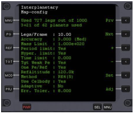
Some basic configurations required by multi-body predictor can be made from the configuration page. In the top edge there is an indicator telling an amount of integration steps used in the prediction. Also, it will tell how many planets are currently included in the computations. For example, "3+5 of 62" indicates that there is three objects fully being used in the calculation and five objects that are using an analytical update out of a total of 62 objects.
Button Layouts and Descriptions[edit]
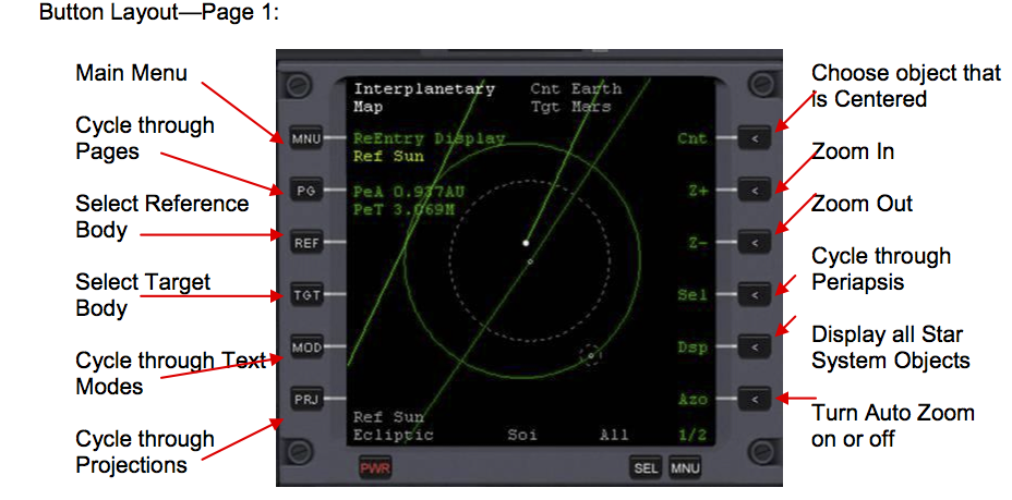
Button Layout—Page 1:
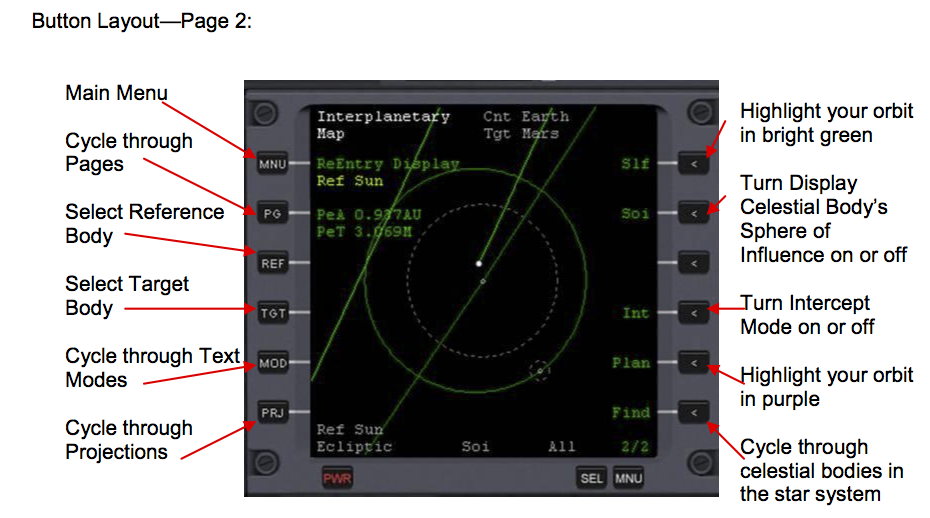
Button Layout—Page 2:
Button Descriptions
MNU — Main Menu
Clicking this button brings up the main menu screen of IMFD.
PG — More Buttons
Switches the right hand side between two sets of buttons.
REF — Set up Reference
Allows the user to set up the reference body.
TGT — Set up Target
Allows the user to set up the target body. There are special options. Inputting "G" targets a geostationary orbit. Inputting "e" targets the ecliptic. Inputting "l" targets the equatorial. Inputting "r" targets the orbit of the reference planet.
MOD — Mode Information Display
Cycle through text modes. There are 3 text modes, plus the map configuration page.
PRJ — Projection
Cycle through projections. There are 5 projections—Self, Ecliptic, Target, Periapsis, and Equator. Self projection uses the current orbit of the ship. Ecliptic projection uses the ecliptic plane. Target projection uses the target orbit for projection. Equator uses the Equator of the target planet for projection. Periapsis uses the ship‘s orbit in a periapsis around Pe. Reference.
CNT — Set up Center
Allows the user to set up the object that the Map Program displays at the center. Inputting "X" centers your vessel. Inputting "p-Target_Name" Centers your point of closest approach to your target body (your periapsis with reference to that target body). Inputting "r-Target_Name" Centers the target body at your closest approach point to that target body (your periapsis with reference to that target body).
Z+ — Zoom in
Zoom in on the object that is currently centered.
Z- — Zoom out
Zoom out on the object that is currently centered.
SEL — Cycle through Periapsises or Apoapsises
Cycles through Periapsises or Apoapsises. There may be multiple Periapsises or even an Apoapsis in your trajectory. When cycling, Pe stands for Periapsis and Ap stands for Apoapsis.
DSP — Body Display
When on, all bodies above the mass limit designated in the Map Configuration Page are displayed. When turned off, only the target body, reference body, reference body‘s orbit, your vessel, and your vessel‘s orbit are displayed.
AZO — Auto Zoom
Automatically zooms so that all items listed in the DSP description are centered and fit nicely into the display. SLF — Self Orbit
When on, your ship‘s orbit is displayed in bright green. When off, your ship‘s orbit is not displayed.
SOI — Sphere of Influence
When on, all bodies displayed have a dotted line around them indicating the boundary of their sphere of influence. When off, no such lines are displayed.
INT — Intercept Mode
Turn Intercept Mode on or off.
PLAN — Course Plan
When on, your ship‘s orbit is highlighted in Purple. When off, your ship‘s orbit is highlighted in green.
FIND — Find Body
Cycles through all bodies in the star system displayed, highlighting their orbits in yellow as they are selected.
Map Configuration Page[edit]
The Map Configuration Page controls how the Map Program runs. To access the configuration page, hit the MOD button until it appears. It is probably best to leave these configurations in their default values unless you must absolutely change them. The only exception to this rule is Accuracy, which must be changed on occasion, such as when you are doing a direct reentry from the moon and you need a perigee prediction with an accuracy of within 2 km at a distance of 250,000 km from Earth, or Mass Limit if you want to use more bodies in the calculation.
Legs/Frame — Number of trajectory legs computed in every time step.
Accuracy — Accuracy of trajectory computations. A higher accuracy requires more CPU resources and produces better results.
MassLimit — The Map Program will ignore all objects with a mass less than this. Exceptions to this are, of course, your spacecraft.
PeriodLimit — Automatically limits trajectory calculation in one full orbit period around the reference planet or moon. Hyper. Limit —Automatically stops trajectory calculation after a flyby.
TimeLimit — Calculate trajectory a specified amount of seconds. This setting will override all other limiters. (0=Disabled)
Tgt WeakPe — Displays flybys even if the periapis is outside a sphere of influence.
One Pe/Ref — When on, the Map Program will display only one periapis passage (the closest one) even if the trajectory will pass by the object multiple times. If disabled, periapis data is recorded for every periapis passage. RefAltitude—Altitude of entry interface.
Method — Order of RK method used in trajectory calculation. Order options are RK 4(5), RK 6(7), and RK 7(8).
Use Celbody — When YES, the Map Program acquires celestial body positions from Orbiter's celestial body interface. Otherwise, the Map Program uses Keplerian orbit elements.
Adaptive — Experimental parameter, must be left in default setting.
Err. Toler — Experimental parameter, must be left in default setting.
Text Modes[edit]
There can be multiple periapsises or even an apoapsis in your trajectory. Text information may vary for these cases. For example, in an Earth to Mars transfer, you will have your periapsis at Mars, your periapsis your solar orbit, and your apoapsis of your solar orbit. You can cycle through these periapsises or apoapsises via the SEL button, and you can cycle through text modes via the MOD button. Below are all abbreviations you will encounter in the Map Program:
| RIn | Relative Inclination to a Node |
| PeT | Time to Periapsis |
| PeV | Velocity at Periapsis |
| PeD | Radial Distance of Periapsis |
| PeA | Altitude of Periapsis |
| Ecc | Eccentricity of Orbit |
| Cir | Delta Velocity required to circularize orbit |
| Tn | Time to next node |
| PlC | Delta Velocity required for the Plane Change |
| GET | - |
| Hed | Heading on the surface of the celestial body |
| EqI | Equitorial Inclination |
| Lon | Current longitude on surface of celestial body |
| Lat | Current latitude on surface of celestial body |
| ApT | Time to Apoapsis |
| ApV | Velocity at Apoapsis |
| ApD | Radial Distance of Apoapsis |
| ApA | Altitude of Apoapsis |
Map Program Display[edit]
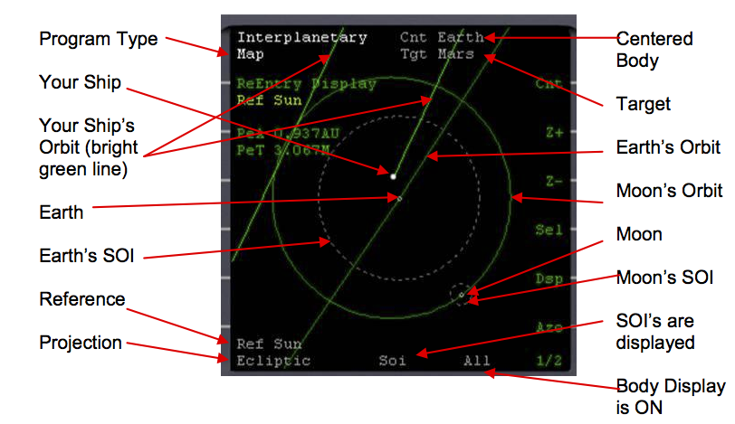
Display Close to a Planet
Here is what the display looks like close to a planet. Here, we are about 3 hours out of Earth Ejection.
Note—Your ship‘s orbit is broken. The line to the left shows your orbit in one solar orbit from where you are now. It is broken because Mars‘s gravity when you pass it (if you don‘t do an insertion burn and just come right back to where you started) distorts your orbit slightly. Note, you will be near where you started if you do this, but Earth will not be there!!! Also note how the ship is inside Earth‘s SOI in the figure above.
Display far from a Planet
Map display with Body Display OFF:
Note: The point of intersection is where your orbit and your target‘s orbit cross AND where a node is. The point of intersection of your orbit and your target‘s orbit below ―Point of Intersection‖ is NOT where you will intercept the target because there is not a node in that location.
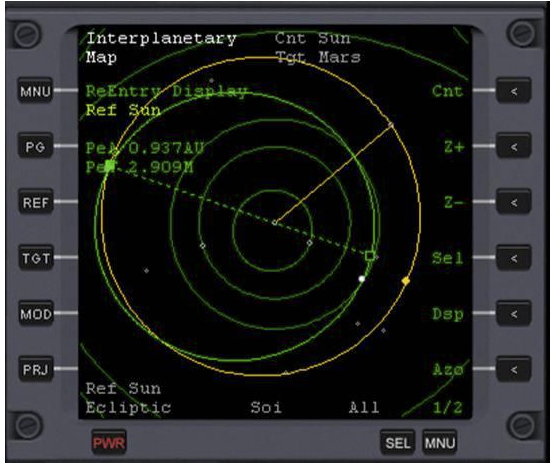
Map display with Body Display ON:
All objects in the display described on the previous page are the exact same. Hitting Dsp turns on all other bodies and their orbits. The bodies‘ orbits are in dull green, while their current positions are displayed by little grey circles.
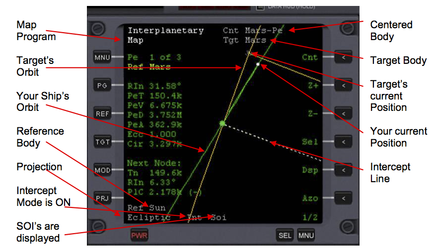
Intercept Mode:
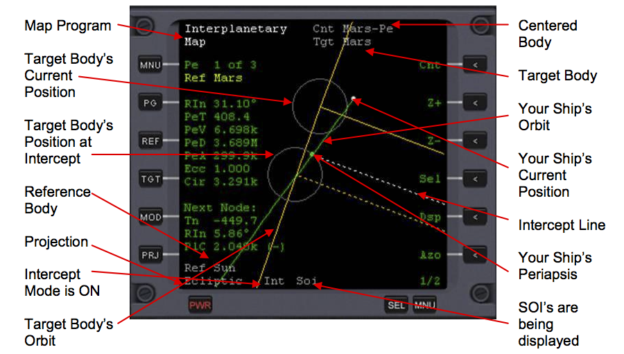
In the below figure we are closing in on our Target, Mars. The Intercept Line (white dotted line) leads to the point of intercept. Note that the periapsis at the target planet MUST be centered in order for Intercept Mode to work.
Intercept Mode: Close up view of intercept
| IMFD Configuration Page | IMFD Manual Contents | IMFD Course Programs |
