Difference between revisions of "GPIS 7: Mars Awaits"
m (Replaced link to scenarios with OrbiterWiki link.) |
(Added category.) |
||
| (3 intermediate revisions by 3 users not shown) | |||
| Line 34: | Line 34: | ||
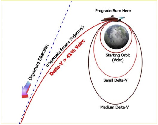
[[File:GPIS_7_2.png|frame|center|alt=Escape velocity|'''Escape Velocity''' – You know from earlier flights that burning prograde at periapsis increases your apoapsis, and the longer you burn, the higher it is raised, making your orbit’s eccentricity increase. When eccentricity exceeds 1.0 (parabolic), the path becomes a hyperbola that approaches but mathematically never reaches a line (asymptote) which is also the departure direction. For a more complete, well-illustrated, and very easy to understand discussion of escape trajectories and many other aspects of orbital mechanics and space flight, see Wayne Lee’s book To Rise From Earth (reference details can be found at the end of chapter 8).]]<br clear=all> | [[File:GPIS_7_2.png|frame|center|alt=Escape velocity|'''Escape Velocity''' – You know from earlier flights that burning prograde at periapsis increases your apoapsis, and the longer you burn, the higher it is raised, making your orbit’s eccentricity increase. When eccentricity exceeds 1.0 (parabolic), the path becomes a hyperbola that approaches but mathematically never reaches a line (asymptote) which is also the departure direction. For a more complete, well-illustrated, and very easy to understand discussion of escape trajectories and many other aspects of orbital mechanics and space flight, see Wayne Lee’s book To Rise From Earth (reference details can be found at the end of chapter 8).]]<br clear=all> | ||
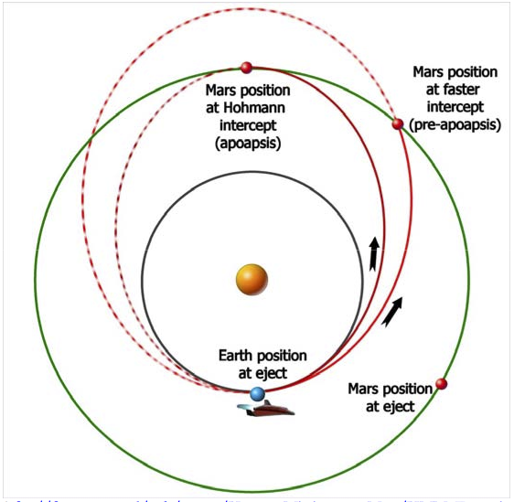
| − | '''Transfer Orbits and Launch Window''' – The minimum energy trajectory to travel from one planet’s orbit to another is an elliptical orbit around the Sun which just touches both orbits; this is called a Hohmann transfer orbit. The Hohmann transfer is also generally the slowest trajectory. For travel to inner planets, the Earth’s orbit is the apoapsis point, and the target planet (e.g., Venus) is the periapsis. If the target planet is farther out, the periapsis of the transfer orbit is at the Earth, and the apoapsis is at (in our case) Mars, as shown in the figure below. A spacecraft on a Hohmann transfer will take 259 days to reach Mars and will move through precisely half an orbit (180°) around the Sun. If you have more available ΔV, non-Hohmann transfers are possible, and these are generally faster. In the figure below, the Hohmann transfer is shown in brown, and the higher- ΔV transfer orbit is red. Note that for the Hohmann case, the intercept occurs at the apoapsis of the transfer orbit, where the orbital speed is minimum, | + | '''Transfer Orbits and Launch Window''' – The minimum energy trajectory to travel from one planet’s orbit to another is an elliptical orbit around the Sun which just touches both orbits; this is called a Hohmann transfer orbit. The Hohmann transfer is also generally the slowest trajectory. For travel to inner planets, the Earth’s orbit is the apoapsis point, and the target planet (e.g., Venus) is the periapsis. If the target planet is farther out, the periapsis of the transfer orbit is at the Earth, and the apoapsis is at (in our case) Mars, as shown in the figure below. A spacecraft on a Hohmann transfer will take 259 days to reach Mars and will move through precisely half an orbit (180°) around the Sun. If you have more available ΔV, non-Hohmann transfers are possible, and these are generally faster. In the figure below, the Hohmann transfer is shown in brown, and the higher- ΔV transfer orbit is red. Note that for the Hohmann case, the intercept occurs at the apoapsis of the transfer orbit, where the orbital speed is minimum, thus requiring less ΔV to slow down for Mars capture than the non-Hohmann case. Withthe Delta Glider, we can largely ignore such issues, since there is plenty of fuel, but with real current boosters, these energy issues are very important for interplanetary flights. |
[[File:GPIS_7_3.png|frame|center|alt=Transfer orbits|'''Transfer Orbits''' – The sizes and shapes of these sample orbits are exaggerated for illustrative purposes. The Hohmann transfer is well known as the minimum energy and slowest transfer orbit, but other transfer orbits are possible. | [[File:GPIS_7_3.png|frame|center|alt=Transfer orbits|'''Transfer Orbits''' – The sizes and shapes of these sample orbits are exaggerated for illustrative purposes. The Hohmann transfer is well known as the minimum energy and slowest transfer orbit, but other transfer orbits are possible. | ||
| Line 302: | Line 302: | ||
|style="text-align:right" width="33%" |[[GPIS_8:_Learning_And_Doing_More|Chapter 8: Learning And Doing More]] | |style="text-align:right" width="33%" |[[GPIS_8:_Learning_And_Doing_More|Chapter 8: Learning And Doing More]] | ||
|} | |} | ||
| + | |||
| + | [[Category: Articles|Go Play In Space 08]] | ||
| + | [[Category:Tutorials|Go Play In Space 08]] | ||
| + | |||
| + | {{HasPrecis}} | ||
Latest revision as of 11:02, 14 October 2022
| Chapter 6: Reentry | GPIS Contents | Chapter 8: Learning And Doing More |
Acknowledgement[edit]
This material was originally contributed by Bruce Irving from the 2nd edition of Go Play In Space. This chapter was written by Andy McSorley. For the 3rd edition, Mark Paton planned to provide a new chapter based on his add-on for the Mars Design Reference Mission. Understandably, development of the replacement chapter has taken a back seat to development of the add-on.
Mars Awaits[edit]
For centuries human beings have dreamt of one day making a journey to Earth’s mysterious neighbor - Mars. This chapter will attempt to guide you on that journey, all the way from the surface of the Earth, to Martian orbit over Olympus base. From there you can take the final step of your journey to the surface of Mars. The flight will take place in a standard Delta Glider, planned and guided with the optional add-on IMFD by Jarmo Nikkanen, starting with the scenario “1. Awaiting Take-off from Canaveral” that comes with this tutorial. Upon arrival in Martian orbit you will have the choice of making a manual or an automatic landing using LandMFD. Either way I will describe what actions to take when the time comes. The flight time in the real world is around 6 months, so I have packed a number of zero-G board games and other activities back in the passenger compartment so you won’t get bored.
The Scenarios necessary for this tutorial can be downloaded here: File:GPIS From Earth to Mars.zip
IMFD v4.2.1 (minor 2006 update, by Jarmo Nikkanen) can be downloaded from here: http://koti.mbnet.fi/jarmonik/Orbiter.html
LandMFD (by LazyD) can be downloaded here: http://www.aovi93.dsl.pipex.com/others_addons/LandMFD0514.zip
Background - Interplanetary Trajectories[edit]
If you are anxious to get flying and want to skip this background material for now, just jump to the heading “Let’s Get Flying.” Make sure you have IMFD installed and activated before launching one of the supplied scenarios.
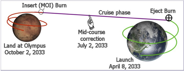
Are you sitting still? Of course not. Even if you’re not reading this in some sort of moving vehicle, you are rotating with the Earth’s surface (464 m/s at the equator), and traveling around the Sun with the Earth in its orbit (29,800 m/s on average). These non-apparent motions give you a much needed boost when you make interplanetary flights, for which you first must typically achieve low Earth orbit (LEO, around 7500 m/s), then fire your engines at the right time and direction to achieve escape velocity. This leads to a transfer orbit around the Sun, carefully planned and timed to intercept the orbit of the target planet just when the target planet arrives at that point in space. As with other orbits, once the transfer orbit is established with the eject burn, you will just coast to your destination (other than a small course correction burn or two). Additional steps are needed to enter into orbit and land at the desired spot on the planet. Orbiter includes tools to support all these steps, but the optional add-on Interplanetary MFD (or IMFD) by Jarmo Nikkanen incorporates most of the required tools and makes the process somewhat easier. But before you start pressing the buttons, you will want to have an idea of what you will be doing.
Planning Your Escape - If you have tried the Moon flight in Chapter 4, you might think you have already escaped from Earth’s gravity, but you haven’t quite. The Moon is also in orbit around the Earth, so a Moon flight is really just a transfer from one Earth orbit to another (very high) Earth orbit. But to go to another planet, you must escape Earth’s gravity and go into orbit around the Sun. If you are already in Earth orbit, you can achieve escape velocity by making a prograde burn that adds at least 41% to your circular orbital velocity (Vcirc). For example, for a circular orbit of 300 km altitude, orbital speed is 7.73 km/s, and to just reach escape velocity, you must add 3.17 km/s for a total of about 11 km/s relative to the Earth. Note that this 41% rule means it takes less absolute ΔV to escape from a high orbit than from a low one, but of course it took more ΔV in the first place to reach the high orbit, so there is no free lunch. In practice, you will add more ΔV than minimum to have some remaining speed (“hyperbolic excess velocity”) when you pass the Earth’s sphere of influence (SOI). Note that upon escape, you will be in orbit around the Sun, and your excess ΔV will add to the orbital velocity of the Earth that you start out with (around 30 km/s).
Transfer Orbits and Launch Window – The minimum energy trajectory to travel from one planet’s orbit to another is an elliptical orbit around the Sun which just touches both orbits; this is called a Hohmann transfer orbit. The Hohmann transfer is also generally the slowest trajectory. For travel to inner planets, the Earth’s orbit is the apoapsis point, and the target planet (e.g., Venus) is the periapsis. If the target planet is farther out, the periapsis of the transfer orbit is at the Earth, and the apoapsis is at (in our case) Mars, as shown in the figure below. A spacecraft on a Hohmann transfer will take 259 days to reach Mars and will move through precisely half an orbit (180°) around the Sun. If you have more available ΔV, non-Hohmann transfers are possible, and these are generally faster. In the figure below, the Hohmann transfer is shown in brown, and the higher- ΔV transfer orbit is red. Note that for the Hohmann case, the intercept occurs at the apoapsis of the transfer orbit, where the orbital speed is minimum, thus requiring less ΔV to slow down for Mars capture than the non-Hohmann case. Withthe Delta Glider, we can largely ignore such issues, since there is plenty of fuel, but with real current boosters, these energy issues are very important for interplanetary flights.
- ftp://ftp.estec.esa.nl/pub/aurora/Human_Missions_to_Mars/HMM_Executive_Summary_Final_Version.pdf (1 MB PDF).
The other important point about transfer orbits is their direction and timing, both of which are closely linked to the relative positions and motions of the planets involved. Since Mars takes 687 (Earth) days to complete one orbit, while the Earth’s year is 365 days, it’s clear that the relative positions of these two planets will change constantly. As with the chapter 4 Moon trip, it is necessary to “lead” the target in order to arrive at its predicted future position, and there are only certain ranges of dates and corresponding planetary positions for which the relative positions of the planets are favorable for an energy efficient Hohmann (or near Hohmann) transfer. These establish the feasible launch windows. For the Earth and Mars, launch windows for such energy favored transfers occur about every 25-26 months (the period varies because the orbits of Earth and Mars are elliptical). Once again the futuristic Delta Glider gives you a wider range of options, and IMFD can plan high-energy flights for situations that would not even be considered for a real flight with current technology. The example flight here is a faster- than-Hohmann case (178 days).
Background – About IMFD[edit]
Interplanetary MFD (IMFD 4.2) is a “space navigation computer” created as an add-on module for Orbiter by Jarmo Nikkanen (http://koti.mbnet.fi/jarmonik/Orbiter.html, version 4.2.1 is a slight modificationforOrbiter2006). ItismoreadvancedthanthebasicTransferMFD,andsimilarinmost ways to Duncan Sharp’s TransX MFD, which was originally an add-on but is now included with the standard Orbiter release package. Both TransX and IMFD allow you to do simple or complex interplanetary flights, and although IMFD has a few special features that TransX does not have, which to use is largely a matter of taste and which one you happened to learn first. There are a number of tutorials for both programs around the web, and many Orbiter web forum members who are familiar with both programs.
We won’t try to summarize all of IMFD’s features, but there are enough to require a more elaborate interface than most MFDs, including a menu selection page for the various programs. These include:
- Course Program – Collection of navigation tools including co-planar intercept, off-plane intercept, planet approach, orbit insert, and a few others less commonly used
- Orbit Eject – Used to plan departure from the starting planet, from either the surface or from a parking orbit
- Map – A powerful and flexible trajectory display and analysis tool based on accurate and fast numerical integration techniques
- Base Approach – A special program for setting up to land at a specific base on the target planet
- Sling Shot – A special program for planning and executing gravitational “sling shot” maneuvers
Only a few of IMFD’s features are used in this tutorial. One that is used a lot is the AB (auto-burn) button found in most of the programs. It will automatically orient and hold the ship in the right direction and fire the engines for the burn. Quite amazing. There are other tutorials that get into more depth, but this chapter will give you a good idea of how powerful yet still easy IMFD can be. There is some “danger” in treating IMFD as a black box that magically gets you to Mars when you press certain buttons, but if you find it fun to plan trips to other planets, you may find yourself digging deeper into more advanced tutorials and background materials, and learning some real orbital mechanics in the process.
IMFD Interface and Terminology – IMFD starts with a menu page that allows you to choose from its main features or “programs” – IMFD is in effect a suite of related MFDs that can share data. Most or all IMFD screens include a PG button that toggles a second set of buttons on the right side of the MFD. Since you may have multiple things to plan and monitor, IMFD also supports a “shared” mode which allows you to display different IMFD screens on the left and right MFD, both based on the same data. Although it is common to have two instances of the same MFD displayed in Orbiter (e.g., two Orbit MFDs referenced to Earth and to Sun), these instances are normally independent.
Many of the terms and abbreviations used by IMFD are common to Orbiter (e.g., PeT, time to periapsis), but some are unique, and at least one is an “old” Orbiter term (PeD for periapsis distance from center of body, which is now PeR for periapsis radius in Orbiter). Any needed terms will be explained as needed in the tutorial steps. Pictures of most of the needed screens will also be shown. In this chapter, buttons to press are indicated by Bold text.
Mars Flight Game Plan – The “game plan” for this 2033 flight to Mars is to use IMFD in both the left and right MFD slots for most of the flight, and to use the modules in the list below. You may find it useful to open up an additional MFD window to hold a copy of the Orbit or Map MFD for general orientation. To do this, you must first activate the ExtMFD module in the Launchpad dialog. Once in Orbiter, press Control-F4 and choose ExtMFD from the list of modules. You can then re-size and move this window anywhere on the screen and set it to any built-in MFD you like (but not IMFD).
Several intermediate scenario files are provided, so you can start where you like.
- General flight plan – This is done with the Off-plane Intercept module of the Course program and will be used to establish your launch time and arrival date at Mars. The information established here will be shared with the other IMFD programs as needed.
- Launch from Earth (scenarios 1 and 1.1) – This phase is guided by the surface mode of the Orbit Eject program (gives you optimal launch time and heading).
- Eject Burn from Orbit (scenarios 2 and 3) – This phase is guided by the Orbit Eject program, where the auto-burn (AB) feature will automatically orient the ship and fire the engines at the proper time for the planned eject to Mars. Delta-V is about 3600 km/s.
- Cruise Phase, Accurate Flight Tracking – This is done with the Map program.
- Mid-course Correction (scenario 4) - This is handled with an auto-burn in the Course program,
using the Map program to see the effect at Mars. Small delta-V.
- Base Approach (scenario 5) – The Base Approach program lets you set up an auto-burn for an arrival orbit that will pass over Olympus Base in preparation for landing.
- Orbit Insert Burn (scenario 6) – The Orbit Insert program actually performs the orbital entry burn that was set up by Base Approach. Delta-V will be almost 2800 km/sec.
- Entry and Landing (scenario 7) – Once you are in an orbit that passes over Olympus Base, IMFD is no longer needed. Steps are provided for landing manually (similar to the chapter 3 and 4 Moon landings) or automatically with the optional LandMFD add-on.
With proper use of time acceleration (discussed in the tutorial steps), this entire six-month flight to Mars can be accomplished in under one hour. Although this chapter and many aspects of this book are a team effort, Andy McSorley is your instructor pilot for the following detailed steps, so follow carefully.
Let’s Get Flying[edit]
To use the supplied scenarios just place the folder ‘From Earth to Mars’ into your Orbiter installations scenario folder. You must also be sure that the two add-ons used in this tutorial have been installed into the Orbiter folder, and have been activated on the “Modules” tab of the Launchpad dialog. If this is not done, MFD screens that should display IMFD will instead be blank (need to quit, activate, and restart).
This tutorial can also be started from Earth orbit, using either Scenario 2 or 3. I have also included an additional scenario 1.1 Awaiting Take-off from Canaveral, which has IMFD already set up. The buttons to click are in bold type. Note that while displayed numbers and times can vary slightly from the ones shown in the screen shots, you should enter inputs as shown (IMFD adjusts for small changes). Be aware that if you begin your flight with Scenario 1.0, the values you see thereafter in IMFD will likely vary from the ones given in this chapter. This is due to the fact that no two users will achieve LEO with identical orbital parameters.
Scenario 1. Awaiting Take-off from Canaveral (April 8, 2033, 1723 UT)
- Open IMFD in the left MFD screen, PWR, SEL, Interplanetary
- Select Menu, switch mode to ‘Shared’ (if not set already), and select the Interplanetary Course program ‘Off Plane Intercept’, MNU, PG, Course, Prv, Set
- Target Mars, TGT – Enter mars into dialogue box – Return
- Select arrival MJD (under TIn), Nxt (x4)
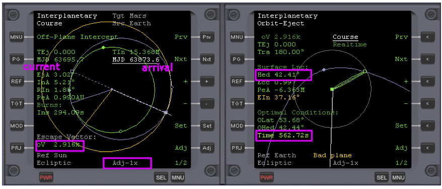
- Set Adj to 10x and use the – button (and + button if necessary) to reduce oV to a minimum value. When you reach the minimum level of oV at the Adj x10 setting, set Adj to x1 and reduce oV further. When you’re finished oV should equal 2.916k and arrival MJD should equal approximately 63873.5. Change it to 63873.6 (for better arrival conditions, same oV).
- Open IMFD in the right MFD screen, PWR, SEL, Interplanetary
- Select Orbit Eject program, and set it to Course, MNU, Orbit-Eject, then + to change ‘Higher Orbit’ to ‘Course’.
- Select MOD (mode) to see the surface take-off heading ‘Hed’ and time to launch ‘Time’.
There are two values of interest here. The first is the nominal heading to fly to orbit on, ‘Hed’, which a few minutes after opening the scenario is about 42.41 degrees (Fig. 1). The second value of interest is the time to launch, ‘Time’, which is counting down at the bottom of the right MFD, and which should be about 700 – 750s (700 - 750 seconds). The aim is to fly to orbit on the given heading, reducing EIn (escape Inclination) to zero (or as near as you can get it) as you ascend.
For take-off you can switch the left side to the standard Surface MFD. For details on how to fly to orbit in the Delta Glider refer to the Earth-to-Moon launch in chapter 4.
Wait, or warp time (10x max) until time to launch, ‘Time’ is zero, and take off.
After take-off point the DG towards the heading shown by ‘Hed’ in the right MFD and fly to orbit (you can vary from Hed by 1° to 5° to try to reduce EIn to zero). Don’t use the right MFD for anything else during the flight to orbit or you will lose the values it contains for heading etc.
Your final orbit doesn’t have to be perfect, just so long as it’s above the atmosphere. As you ascend, the Escape Inclination ‘EIn’ figure will start to reduce in the right MFD. If you fly perfectly it should be very close to zero by the time you reach orbit. If you don’t, you can adjust it later in orbit.
Scenario 2. In Earth Orbit (April 8, 2033, 1848 UT)
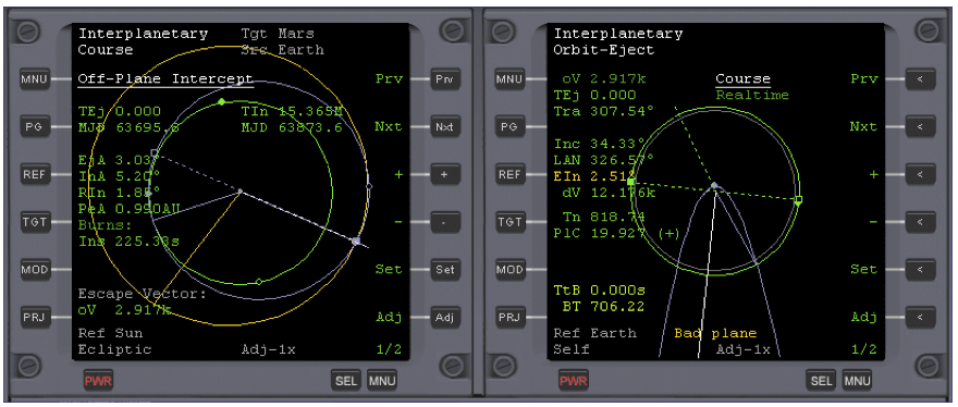
This scenario opens with IMFD open and set, but you have to reduce EIn to zero as described below, before setting off to Mars. See Fig.2.
If surface mode data (Hed etc.) are still displayed, select MOD to switch it off and display PlC, TtB (time to burn), and BT (burn time, i.e., duration) instead. If EIn is much above zero, you will first need a plane change burn, indicated by PlC (seconds). The + or – next to the PlC (magnitude of plane change burn) denotes the direction in which to make the burn. Turn your spacecraft’s attitude to ‘+Normal’ or ‘-Normal’ (in this case it’s +). Wait until Tn (Time to node) has counted down to zero before firing the main engines to drive EIn to zero (or very close). An example of this is provided in scenario ‘2. In Earth Orbit’. Here EIn is 2.51 degrees. To reduce this to zero as described above, you will complete about a quarter of an orbit (818.74 seconds in Figure 2 below), with about a 20 second +Normal burn required.
Make the burn when Tn reaches zero, for the duration (PlC) seconds at full thrust, but be aware that full thrust may not be necessary when only a small burn is needed, as it increases your chances of overshooting your target, so go easy on the gas here. Cut the burn when the Escape Inclination ‘EIn’ has reached zero.
You are now ready to continue to the next stage of the flight, which is to eject from Earth orbit towards Mars, beginning at step 1 below.
Scenario 3. In Earth Orbit, Eln Zero (April 8, 2033, 1904 UT)
Assuming that you have ascended to Orbit and EIn (escape inclination) is zero, carry on beginning at step 1 below. If you want to just fly to Mars with a minimum of set-up then use this scenario to begin your mission at step 2 below.
- If you had closed IMFD in the left MFD screen, reopen it, Select, Interplanetary
- Select MOD – only if Hed, etc. (surface mode) are still displayed on the right MFD
- On the right MFD select Realtime and change it to Prograde, Nxt, +
- Orbit Eject now displays updated Time to Burn (TtB) and Burn Time (BT) values.
- In the Orbit Eject (right MFD) program select Auto-burn, PG, AB
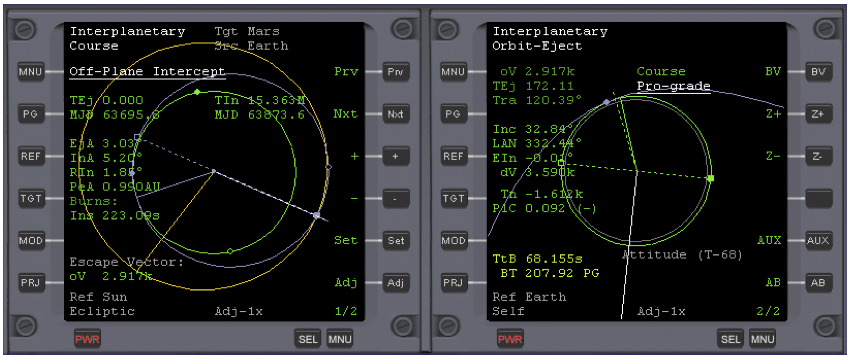
Now wait, or warp time (100x max) until about 30 seconds before TtB equals zero, then return to normal time. See Fig. 3. Note that as early as three minutes (T-180) before burn time, the auto-burn controller will start to fire RCS thrusters to orient the ship for the burn. This is normal. You can view the burn alignment cross-hair display with the BV button (click it again to return). This can also be used to manually set and hold orientation in cases where AB doesn’t work well (e.g. for some slowly-responding add-on ships).
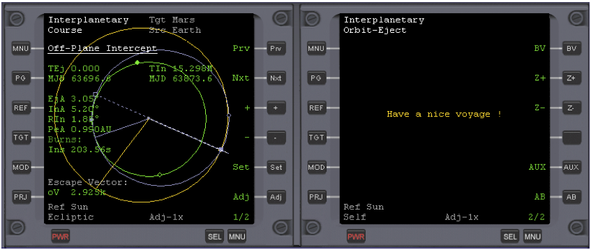
The eject burn for Mars will begin automatically. When the burn has completed, warp time (1000x max) until you have left Earth’s gravitational sphere of influence, ‘Soi’. You will be able to tell when this has happened when the RH MFD displays the message ‘Have a nice voyage!’
When you see the “nice voyage” message, return to normal time.
- In the left MFD set the source ‘SRC’ to self, PG, Src, Enter ‘x’ .
This is important: you will need to use the Course program to make a correction burn later, and it must know the source object to make the correct burn calculations.
This updates the Course program’s source orbit from Earth to your own spacecraft. Now you can see your actual trajectory (green), superimposed over the calculated HTO hypothetical transfer orbit (blue). You will now be able to monitor the progress of your voyage using the Course program, and later use it to make a small mid-course burn to correct your trajectory. See Fig. 4.
We have no further need of the Orbit Eject program in the right MFD so we can replace it with IMFD’s Map program, an extremely powerful and accurate tool. So let’s do that.
- MNU, Map, Ref (enter ‘mars’), Cnt (enter ‘x’)
- Display the orbits of the planets and their spheres of influence, Dsp, PG, Soi
Here are the main buttons for the Map program:
- PG - Toggles button functions
- Z+ Z- - Zooms in and out of the Solar System map
- Cnt – Lets you choose what object (planet, Moon or Spacecraft) is at the center of the display
- Dsp - Toggles the display of the planetary orbits
- Soi - Toggles the display of the planet’s gravitational sphere of influence
- Azo - Auto-zoom On/Off. Lets you choose whether the Map program adjusts its display automatically when changing Reference, Source etc.
- Ref - Sets the reference object from which the orbits and trajectories are displayed.
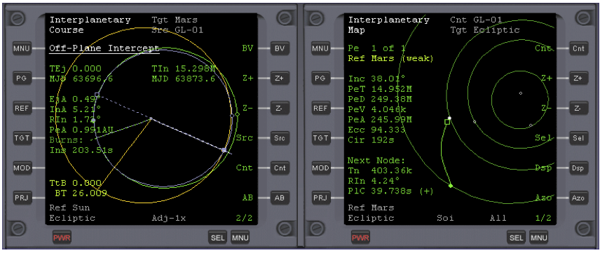
Make yourself familiar with this now; you will need to be able to use it as you approach Mars. When you’ve finished, your MFD should look something like this below. See Fig. 5.
As a matter of interest, if you zoom out the Map, you may notice a slight discontinuity in your trajectory at the point where the Earth’s influence begins to diminish and the influence of Mars begins to take over. Changing ‘reference’ in the map program enables you to see your orbit from the ‘referenced object’s’ position. Change the reference to Sun, and you will see a trajectory similar to that in the Course program, but more clearly. It’s roughly at the slight bend of your trajectory, where the effect of Mars’ gravity begins to be felt, that you will make a correction burn.
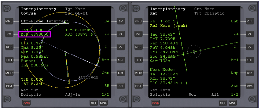
Now let’s make some progress towards Mars. Warp time (T x 5, 100,000x) until just before the halfway stage of the flight, around MJD 63780. Use Map Z- to zoom out to see your progress.
| Using Time Warp
At time warp 100,000x, each second is roughly equivalent to about one day of real time (which is actually 86,400 seconds). So from the time of leaving Earth’s SOI to the time when you need to make the correction burn, it takes about 73 seconds of simulator time. In the real world this is equivalent to 84 earth days. The total ‘real’ time for the journey is 178 days (about 6 months). You can’t do the whole thing at 100000x, of course – such extreme time warp is only safe in cruise phases (no burns or autopilots). Orbiter can’t keep up! |
During the time warp you will also notice that from the point where you set the course program source to ‘x’ - your spacecraft, the BT displayed has decreased from about 26 seconds (see figure 5) to around 3 seconds then begun to increase again to around 5-10 seconds.
Slow time warp to 100x as current MJD approaches MJD 63780 (upper right corner of Orbiter display), and then return to normal time once it is reached.
Scenario 4. - Correction Burn (July 2, 2033, 84 days into flight)
Now it’s time to make another burn to correct the errors that will have inevitably occurred on a trip of this distance. You can see the duration of the burn that’s necessary, by observing the value BT at the bottom of the left MFD, usually somewhere between 5-10 seconds. See Fig. 6.
Before you do though, set the Map program to reference Mars (if not already, REF), and also center the display to Mars (Cnt) to see the resultant effect of the correction burn. Zoom in a few times with the map and you will notice that your trajectory is some way off from the position of Mars.
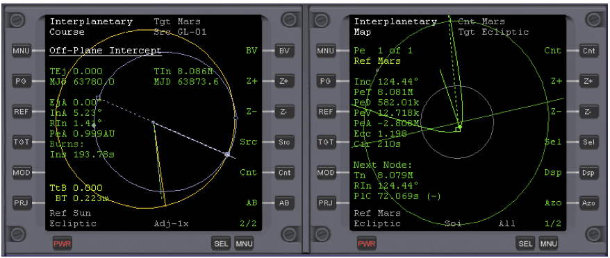
To make the burn just click AB, and IMFD’s Course program will do the rest.
The accuracy of the burn may vary, but it will usually place your trajectory close to or within the orbit of Mars’s outer satellite Deimos. If you’re lucky, you will see your trajectory heading straight towards Mars. See Fig. 7.
After the burn is complete, set the screen to visual aids (“planetarium”) mode F9 (to show labels for the planets, use CTRL-F9 to select which object labels are displayed, displaying the blue line of the ecliptic can be very helpful) and place the spacecraft in a prograde attitude. Now switch off prograde and rotate your spacecraft to the left. Mars should come into view. Kill-rotation when it is in the center of your screen. If you don’t see Mars, you will have to hunt for it (check the external view), but eventually you’ll find it. When you do locate it kill-rot.
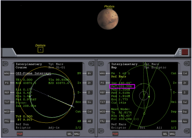
Now warp time (100,000x), until Time to Periapsis (at Mars) PeT in the right MFD is around 500k (seconds). Then slow time warp to 10,000x and then lower still as you approach 100k. Be very careful, as it’s easy to overshoot your target. When PeT is 100k, return to normal time. Now if you are still facing towards Mars, and you zoom the field of view to 10 degrees, you will be presented with your first sight of Mars (see Fig. 8, PeT 101.35k). Return zoom level to its previous setting.
Scenario 5. Base Approach (October 2, 2033, 176 days into flight)
The Course program in the left MFD is now finished with, so we can use the MFD on this side to plan a low parking orbit around Mars that will place us over Olympus base.
To do this you need to enter the coordinates of the base into IMFD’s Base Approach program as well as some other data. The Base Approach program will set your periapsis distance (for either a prograde or retrograde orbit), orbital alignment (with the base), and the number of orbits to complete after insertion, before you pass over the base.
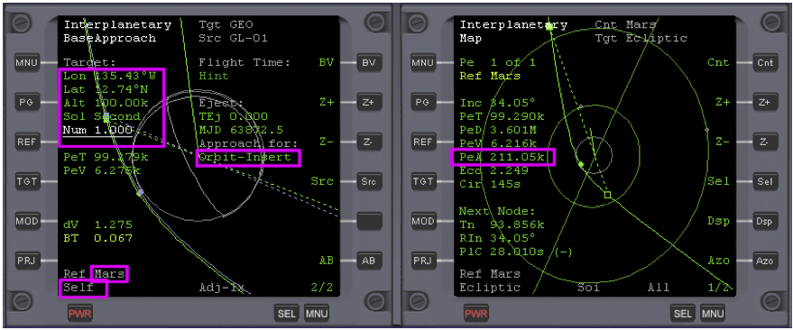
Open the Base Approach program in the left MFD, MNU, Base Approach, Nxt (x3), then + (x2) until ‘Approach for:’ changes to ‘Orbit Insert’. Then (see notes at end of the chapter),
- Reference Planet: REF, enter 'mars'
- Projection: PRJ – Change to ‘Self’
- Longitude: Nxt, Set (enter 224.57) (Olympus base co-ordinates are 135.43W, 12.74N, so why enter 224.57 instead of 135.43? Well, IMFD only accepts coordinates in an Easterly direction, so we have to subtract 135.43 from 360 (degrees) to give us 224.57E, which is the same as 135.43W.)
- Latitude: Nxt, Set (enter 12.74)
- Altititude: Nxt, Set (enter 100k) to set Altitude of Periapsis (don’t forget the 'k'!)
- Sol: Nxt, ‘+’ Change Sol from ‘First’ to ‘Second’. This changes the approach from a
retrograde one to a prograde one. For a prograde approach, the blue HTO will be on the left of the planet. ‘First’ and ‘Second’ refer to the two solutions that are possible.
- Num: Nxt, ‘+’ Change Num from ‘0’ to ‘1’. This allows us to make one complete orbit of Mars before we are perfectly aligned with the base. (In other situations I have left this set to zero (the default setting) and the Base Approach program placed me over Olympus ready to make a descent just after orbit insert was complete. However I find that with this particular scenario, IMFD can’t quite find the burn vector and begins to hunt, never quite making it. This may be because the orbit insert burn occurs to close to the base co- ordinates.)
- Engage auto-burn: PG, AB
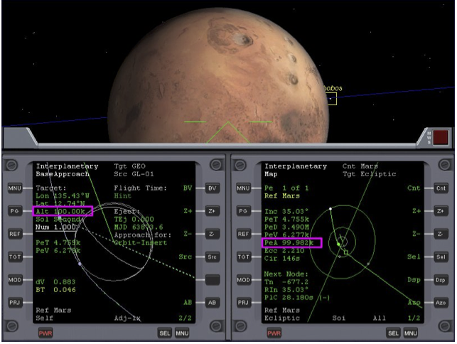
After the burn has taken place (see fig. 9), note how the Map program displays a different (and more accurate) value for PeA, compared to ‘Alt’ (Altitude), which you set in the Base Approach program. We will refine the base approach when we are closer to Mars with another burn.
| Fine Adjustments
Outside of a planet’s sphere of influence, the planet approach program is less accurate at setting your PeA, but the map program gives a very accurate reading. So maintaining the attitude set by the last burn, use linear thrusters (6/9) to fine-tune the PeA value shown in the Map program to 100k (100 km). See how your spacecraft’s trajectory (green) now aligns perfectly with the HTO (blue) trajectory in the Base Approach program. |
Face towards Mars like before. Zoom out the Map in the right MFD 5 times, until you see your spacecraft’s marker (the white dot) and Mars’ SOI. Warp time (10,000x max) until you see the white dot enter Mars’s sphere of influence. Slow down time warp to 1000x. Zoom in with the Map program as you approach Mars. When the white dot reaches the orbit of Mars’s outer moon Deimos, slow to normal time. Now perform another auto-burn AB to refine your base alignment. See Fig. 10.
Note how the Map program’s PeA reading is still slightly different from the ‘Alt’ figure set in the Base Approach program. You can use linear thrusters to refine this to the required number as described in ‘Fine Adjustments’ above.
Scenario 6. Orbit Insert (October 2, 2033, 176 days into flight)
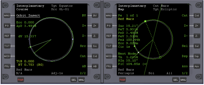
Open the Orbit Insert program in the left MFD, MNU, Course, Nxt (x3) (underline Orbit Insert), Set, PG, AB. Set map to Periapsis, PRJ. See Fig. 12.
Warp time (100x max), zooming the Map program as you approach Mars. Sixty seconds before the insert burn time is reached (TtB), return to normal time (IMFD will reduce warp to 10x before 60s). RCS thrusters will fire before the burn, and after it’s complete, you’re in Martian orbit. See Fig. 11.
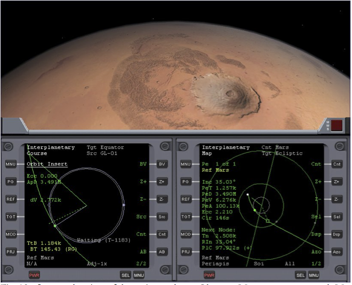
Fig. 12 - Spectacular view of the extinct volcano Olympus Mons, as you approach Mars. Three times the height of Mt. Everest at 27km; it is the largest mountain in the Solar System.
The following scenario options begin at the state shown in fig.13, just after orbit insert. For a manual landing follow the procedure as outlined in the section “Bringing It All Back Home (De- orbit)” of Chapter 3, using the figures in the paragraph below to time the retrograde burn. You may want to display the Surface HUD and/or Surface MFD even for automated landings.
Scenario 7. Preparing to Land (Manual)
Make a retrograde burn at full thrust when 400 km from Olympus Base until your velocity is about 130-150m/s. The descent will be steeper than that used for the Moon as we begin at a higher altitude due to Mars’s atmosphere. The IDS and XPDR frequencies for pad 1 Olympus base have been set in all the scenarios, so opening the VOR/VTOL (Landing) MFD will show you everything you need to know, to make a successful landing. It will begin to give you readings when you get to within 25km of the base. Be sure to lower the gear (G) just before landing.
Note also that Mars’s atmosphere is very thin and it’s not much use to us as an aero-brake. The Delta Glider has plenty of fuel to slow down with anyway.
Scenario 7. Preparing to Land (Using LandMFD)
- Open LandMFD on the left side, SEL (two times), LandMFD
- Warp time (100x max) until LandMFD, which until now has displayed a message in red ‘Too far off plane’ changes to ‘Waiting for PDI ...’ ‘Press <shift> 0 to select Autopilot’. Now slow to normal time (PDI is ‘powered descent initiation,’ an Apollo era term).
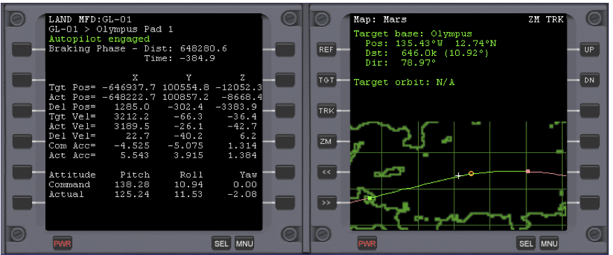
- Engage LandMFD with Shift + ’0’ (zero) and warp time (10x max) until PDI Time: = 120 (seconds) when LandMFD will begin to commence the landing. Slow to normal time (Figure 14 shows LandMFD in the braking phase, about 648 km from Olympus Base).
- When very near the base, lower the landing gear with the G key (not automatic).
Fig. 13 (Note: Use LEFT-shift-0 to engage autopilot if LandMFD is on the left as shown here)
| A Couple of Things About LandMFD
Even though your orbit appears to pass over Olympus base, LandMFD will probably tell you otherwise, with the message ‘too far off plane’. Don’t worry about this, as after one orbit the problem will right itself, usually when you are about 2-3 squares on the Map MFD away from the base. Also note that even when the base alignment is correct and you are more than half an orbit away from passing over the base, LandMFD gives the message that you are moving away from the base. Just bear with this until you finally reach the half orbit before your final descent. |
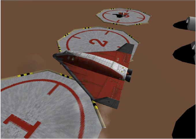
Fig. 15 - The Delta Glider arriving at its destination Olympus Base – Mars.
So now you’ve arrived, and there’s two months leave to take. But what’s this? “All leave cancelled!?!” You’re to immediately take the DG 2, waiting on pad 3, to transport two mining engineers to the asteroid “3200 Phaethon.” And what’s more, you first need to find* and install the add-on to place this and two other Mercury-crossing asteroids in Orbiter’s Solar System so you can fly them there. Great joy!
- http://www.orbithangar.com/advsearch.php?search=name&text=crosser (Mercury Crosser Asteroids by NightHawke)
Bonus Scenarios[edit]
Scenario 8. LandMFD Engaged
Launch this scenario and watch LandMFD make the complete landing.
Scenario 9. Final Approach
Launch this scenario and watch LandMFD make the final approach to Pad 1. The landing gear is already down. With this, you can see the Delta Glider just about to land at Olympus base (Fig. 15).
Things to Try[edit]
You may have noticed that the DG is a pretty small spacecraft for a 6 month flight. You may also wonder if it’s possible to save fuel at any point – ever hear of aerobraking? Here are a couple of ideas for things to try using additional add-ons that are available on the web.
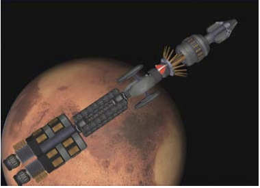
Fly Something Big – Long space voyages will require more living space than the DG has, and eventually there will be some really big ships. Care to upgrade to something in a full-size fusion- powered ship? The Vespucci-D by John McCain and “Oz” is cool, though the propulsion system has a learning curve (read the manual!). Yes, that’s a Delta Glider docked near the rotating habitat modules (for surface ops). Another big interplanetary ship is Deepstar 1.0 by Alain Hosking. With the Scenario Editor and IMFD, you can cruise the Solar System... http://www.orbithangar.com/advsearch.php?search=name&text=vespucci_D http://www.orbithangar.com/advsearch.php?search=name&text=deepstar
Use Mars’ Atmosphere - Unmanned probes can save fuel by using Mars’ atmosphere to adjust their orbits (aerobraking – aerocapture is also possible but as yet untried). The AeroBrake MFD by ‘gp’ (Gregorio Piccoli) can help with this. We haven’t tried it yet, but you can! Note that Mars’ atmosphere ends at 100 km in Orbiter (there’s not such a sharp cutoff in real life). http://www.orbithangar.com/advsearch.php?search=name&text=aerobrak.
| Chapter 6: Reentry | GPIS Contents | Chapter 8: Learning And Doing More |
Precis[edit]
This article has a precis and appears in the Random addon or Random article section on the Main Page. The precis can be found at GPIS 7: Mars Awaits/precis and is displayed below.
|
Go Play In Space, Chapter 7. Go Play In Space is the classic introduction to Orbiter for new orbinauts and those looking to expand their horizons. The Solar System awaits! Chapter 7 takes you from Earth to Mars, teaching the skills you need to reach any planet. (More...)
|
