Difference between revisions of "GPIS 5: Dancing In The Dark"
(Original from GPIS 3rd edition) |
m |
||
| Line 266: | Line 266: | ||
: If you get substantially out of alignment when within DST 75 m or closer, it’s best to back up to 100 m or so, reduce separation rate to near zero, and fix your line-up, then start to move in again. It’s quite hard to fix a bad alignment when you are very close – as with a good landing in an airplane, the secret of good docking is a good approach. Congratulations on docking! | : If you get substantially out of alignment when within DST 75 m or closer, it’s best to back up to 100 m or so, reduce separation rate to near zero, and fix your line-up, then start to move in again. It’s quite hard to fix a bad alignment when you are very close – as with a good landing in an airplane, the secret of good docking is a good approach. Congratulations on docking! | ||
| − | : [[File: | + | : [[File:GPIS_5_16.png|alt=Docking]] |
== Summary of Steps (Dancing in the Dark) == | == Summary of Steps (Dancing in the Dark) == | ||
Revision as of 14:04, 1 January 2015
| Chapter 4: Fly Me To The Moon | GPIS Contents | Chapter 6: Reentry |
Acknowledgement
This material was originally contributed by Bruce Irving from the 2nd edition of Go Play In Space. Refer to the page's View History tab to see subsequent changes.
Dancing in the Dark
Rendezvous & docking is a fundamental and practical application of orbital mechanics. The Apollo Moon landing missions (1969-1972) depended on the ability of the Lunar Module (LM) to launch from the Moon and rendezvous and dock with the Command and Service Module (CSM) waiting in lunar orbit. A major goal of the earlier Gemini program (1964- 1966) was to prove the feasibility of this key technique for the Apollo program. Dr. Edwin E. “Buzz” Aldrin actually did research and development on rendezvous and docking techniques in his 1963 doctoral degree work at MIT before becoming an astronaut and putting the techniques to the test on Gemini 12 (1966) and on Apollo 11 (1969), when he became the second man to walk on the Moon. Nowadays, U.S. Space Shuttles and Russian Soyuz and Progress unmanned supply ships rendezvous and dock with the International Space Station (ISS) to transfer crews and supplies.
In this chapter, you will again fly the Delta Glider to learn how to rendezvous and dock with the ISS in Orbiter. You will use the Scenario Editor to create the starting point for the mission, and the Synchronize Orbit and Docking MFD’s will guide your way to the ISS. There is also a 36 minute annotated flight recording that you can watch to get a feel for the whole process, interrupting it at any time you feel like taking the controls yourself to complete the process.

Requirements for Rendezvous
To rendezvous with an orbiting target spacecraft, there are several important requirements:
- Orbital planes must be aligned to within 1° and preferably to 0.5° or smaller. This is accomplished with the help of the Align MFD as shown in earlier chapters, or in this case by setting the orbital inclination directly with the Scenario Editor.
- The orbits of your ship and the target must be made to intersect at some point.
- Your orbit must be adjusted to “synchronize” with the target’s orbit, meaning that the orbits not only intersect, but that both ships reach the intersection point at very close to the same time.
Although these requirements could be met by trial and error using only the Orbit MFD, the Synchronize Orbits MFD (Sync MFD for short) allows you to choose from several intersection options and to “look ahead” several orbits to check for intersections or near-intersections. The Orbit MFD is still important because the Sync MFD only considers angular position around your orbit, not orbital height. It could show you at the intersection point even if the target is many kilometers directly above or below you (this is a fairly common error in learning to rendezvous and dock).
One question you might have is why we’re not using the Transfer MFD as was done to “rendezvous” with the Moon. In fact you could and probably would want to do this to start with if you needed to rendezvous with a target in an extremely different orbit from your starting orbit, such as LEO (low Earth orbit) to GEO (geosynchronous orbit). In that case you might start out with the Transfer MFD and then use the Sync MFD to guide you in making the adjustments required to achieve the precise intercept necessary for rendezvous with a small target.
A Basic Rendezvous Method
As with most things in Orbiter, there are several ways to rendezvous and dock, and the Sync MFD provides multiple intersection options to support these multiple methods, although all the methods are generally similar to use. We have decided to follow the example of Jared “Smitty” Smith’s excellent “Orbital Operations” tutorial (http://smithplanet.com/stuff/orbiter/orbitaloperations.htm) and use the periapsis/apoapsis method. This has the advantage that it cleanly separates the setting of the intersection point and the orbital adjustments needed to achieve “sync.” It is not necessarily the fastest method, since one or more orbits might be “wasted” getting to periapsis or apoapsis when an alternate intersection point might be available sooner. But it builds on your knowledge of the properties of burns at periapsis and apoapsis and uses only prograde or retrograde burns (assuming that orbital planes have already been aligned). In this case, periapsis is chosen, but apoapsis also works well as a reference point.
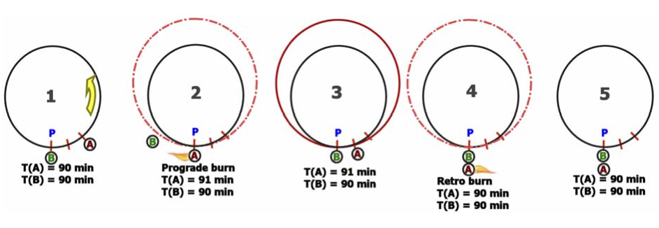
In the figures below (assumed in-plane, not to scale), ship A is you, and ship B is the target (ISS), which is assumed to not maneuver at all. The sync problem is shown schematically. In figure 1, the two ships are in the same circular orbit, but at different angular positions (orbital longitudes) such that your ship A always passes reference point P two minutes sooner than ship B (the target).
It’s clear that with the same orbital period , T(A)=T(B)=90 minutes, the two ships will never “catch up” witheachother.Somethinghastochange. IfyourshipAmakesasmallprogradeburnatP(figure2), this burn point becomes its periapsis, and its orbital period is increased by (say) one minute. The other figures show what happens as a result on the next two orbits. By “speeding up” with a prograde burn, you now have a bigger elliptical orbit that takes one minute longer to complete than the target’s (B) still- original orbit. So on each orbit you “fall back” by one minute. After two orbits, you have fallen back by two minutes and now reach the point P at the same time as the target ship B (figure 4). To prevent falling back further, you would need to make a small retro burn at P to return to the original smaller circular orbit (velocity as well as position matched or “synced” with the target, figure 5). In general, it won’t be quite this simple. Both orbits would probably be elliptical, the difference in arrival time won’t be a simple number like 2 minutes, and the adjustment burn to match orbits with the target when you get near it won’t be a simple retro burn. But the Sync MFD handles the numbers to allow you to line up the times pretty easily for the general case.
Docking Notes
Rendezvous or orbit synchronization can get you close to your target (within a few kilometers or even closer), and then the docking HUD and Docking MFD will help you with the rest. The first job once you are close in position is to also get yourself close in speed, adjusting your relative velocity to make your orbit closely match that of the target . Symbols projected on the docking HUD show you relative velocity as well as position information, giving you visual cues on where to point and thrust to reduce your relative velocity, and on where you are heading relative to the target. Unless your orbit is almost exactly the same as the target’s when you get close to the target, you will find that it can take several cycles of reducing relative velocity, pointing and thrusting toward the target, adjusting alignment, and again fixing up the velocity. Although the HUD and MFD give you good feedback, “keeping everything happy” can seem like a juggling act at first. The details are easier to explain with an actual example, coming up shortly. It can also help to watch the flight recording, which realistically shows how this can all work. An expert could probably make a faster, more efficient, and more accurate approach than what is shown in this recording, but this way you can learn from those mistakes as well!
Setting Up
In the case of the Space Shuttle docking with the ISS, available delta-V is very limited and orbital plane alignment with the target and preparing for a close intersection are done mainly by choosing the right launch window and flying a precise ascent. Using the Delta Glider, you have plenty of delta-V, and you could start with nearly any LEO situation and make the necessary burns to align orbits, rendezvous, and dockwiththeISS. Butinthiscasewewillshowyouadifferentsetupmethodthat’spossibleonlyin Orbiter – the Scenario Editor.
The Scenario Editor has many capabilities and is explained in more detail in Appendix B and in its own PDF manual installed in the Orbiter /Doc folder. In this case you will use its ability to directly change the orbital elements of any spacecraft in the currently running scenario, starting with a scenario where you are already docked and modifying it to put the DG in a different starting orbit. We will give the basic steps here without explaining too much about the orbital elements or the Scenario Editor.
| Flight Recording
An annotated flight recording of this chapter (DG-ISS Sync-Dock.scn) is installed with Orbiter in the Scenarios/Tutorials folder. This scenario already includes the setup steps shown here, so if you wish to skip the setup steps, you can start with the playback scenario instead, using the Control-   “Stop” button to interrupt playback at any time you wish to take over manually and follow the steps in this chapter yourself. If you play back the whole thing with the time acceleration as recorded, it will take 36 minutes. |
- Start Orbiter and activate the Scenario Editor in the Modules tab.
- The module is called ScnEditor and it is not active by default. Select it in the list of available modules and click the button to add it to the active list on the left. Once you do this, Orbiter will remember this setting for future sessions.
- On the Scenarios page, check the “Start paused” check box and launch the scenario “DG Docked with ISS,” in Delta-glider folder.
- Yes, it’s already docked, but you will soon change that. Starting in pause will allow you to change the conditions of the scenario before anything moves.
- Press CTRL-F4 and launch the ScnEditor module from the dialog box.
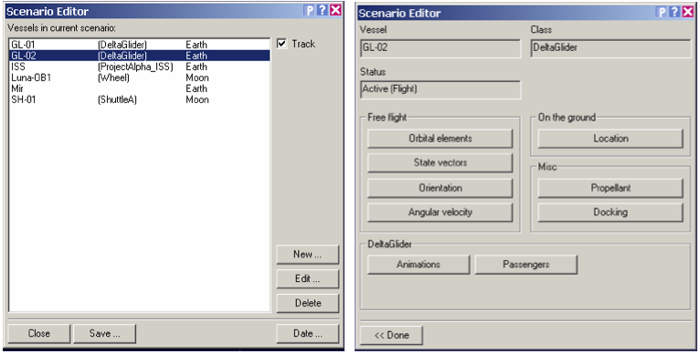
- See below left (main page). Note that the current ship GL-02 is already selected for editing.
- Click the [Edit] button, then on the edit page, click the [Docking] button.
- The edit page is shown above right – it’s mostly selector buttons.
- On the Docking page, click the [Undock] button, then click [<<Done].
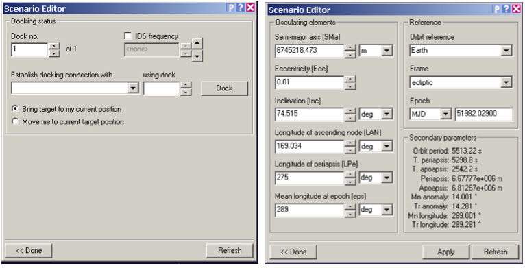
- See below left (after clicking Undock). Nothing visible happens yet (simulation started paused) but Orbiter can now move the DG independently of the ISS.
- Back on the edit page, click the [Orbital elements] button.
- Enter the numbers in the table below.
- Be careful to keep the text cursor in the editor window. Note that most of these values are pretty small changes from the starting (ISS) orbital elements, since we are keeping the new orbit pretty similar, as if we had launched from a good launch window to give good alignment and a fairly small (8°) angular difference in orbital position. Since you will need only relatively small burns to complete the rendezvous, a similar setup could also be used for docking practice with the Space Shuttle Atlantis (which could even be added in the Scenario Editor). You might want to practice with the DG first since the Shuttle has a few special challenges for docking, including a docking port that is on top instead of in the nose.
| Element | Description | Value |
|---|---|---|
| SMa | Semi-major axis (orbit size parameter, meters) | 6745218.473 |
| Ecc | Eccentricity (deviation from circular) | 0.01 |
| Inc | Orbital inclination ("tilt" of orbital plane), deg | 74.515 |
| LPe | Longitude of periapsis (angular position of periapsis), deg | 275 |
| eps | Mean longitude (measure of position around orbit), deg | 289 |
- Click [Apply], then [<<Done] and finally the [Close] button to exit the editor.
- Before you close, you may want to click the [Save] button and save a copy of this starting point for later use. The Save dialog allows you to enter a name and description for the scenario.
- Press Control-P to take Orbiter out of pause.
- Press F8 to change to the no-panel view.
- This is not critical, so use the 2D panel or virtual cockpit view if you prefer, but visibility for docking is a lot better with the no-panel view, and all the critical buttons are available there (the no-panel view is also available for any spacecraft – many add-on ships have no panels).
- On the right (Orbit) MFD, click the [DST] button.
- Orbit MFD is good to keep on the right to start, and DST sets it to display altitude (Alt, PeA, ApA) instead of radius (Rad, PeR, ApR), which is a little more convenient for most things.
- On the left MFD, click [SEL] then [NAV/COM] and define radio frequencies.
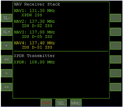
- Highlight a frequency with the [SL-] and [SL+] buttons, change the integer part (108 to 139) of the selected frequency with [<<] and [>>], and change the fractional digits (.00 to .95) with the [<] and [>] buttons to match the picture below (it may not display the IDS info now).
- On the left MFD, click [SEL] then [Sync Orbit].
- On the Sync MFD, do the following two setup steps.
- 1. Click [TGT] then choose or enter ISS.
- 2. Click [MOD] a few times until Sh Periapsis appears at the top left.
You may want to do a Quicksave (CTRL-S) now to include the MFD and frequency information. It’s time to learn how to get back to the ISS where you started out a few minutes ago.
Rendezvous
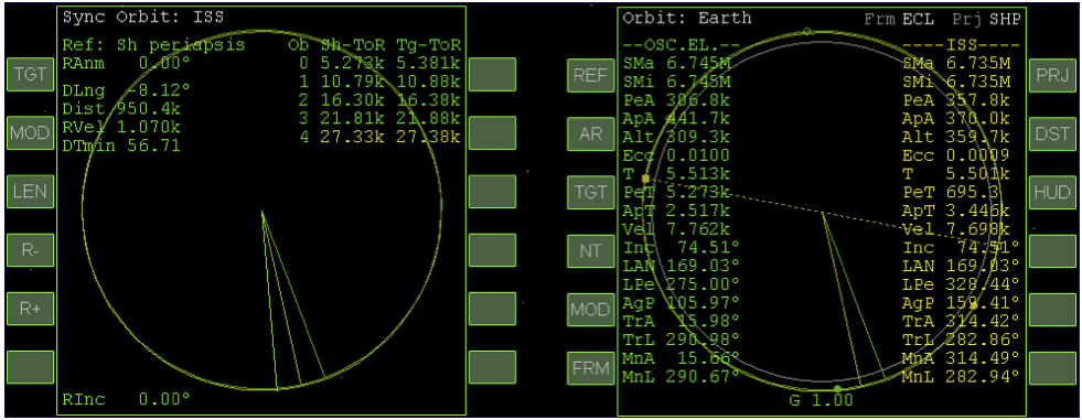
Take a look at the Orbit MFD above right, and you’ll see that as expected, your Delta Glider is now in a slightly different orbit from that of the ISS, giving you a couple of problems to solve. If you have done the scenarios in the earlier chapters (or have other Orbiter experience), you will see some familiar values on the Orbit MFD (note the differences between the DG and ISS orbits above, especially PeA, ApA, Ecc, and T). Note that the radius vector for your ship (green line) is a few degrees ahead of that of the ISS (yellow line), and both have just passed your periapsis (solid green dot).
That Syncing Feeling - In fact the Sync MFD tells you that in the recorded flight, your angular position is 8.12° ahead of the ISS position (difference in longitude, DLng). Note also that the ISS has already passed your periapsis, which we have chosen as the intercept reference point (Ref) in this case. This means you will have to go around almost a full orbit before the ISS will again reach your periapsis, where you will note and write down its altitude (Alt) so you can later adjust yours to match it. You will want to use time acceleration to speed through a couple of orbits before you will have everything set to dock.
Another important thing to note on the Sync MFD is the table on the upper right, with orbit numbers (Ob) zero to four, and columns for Sh-ToR (ship time on reference, your periapsis in this case) and Tg- ToR (target time on reference). None of the Sh and Tg values matches exactly, and we need them to match somewhere in order to dock. In the screen above, they come closest four orbits (or five, depending on whether you count orbit zero) in the future, on Ob 4. How close? That’s the value DTMin (delta-time minimum), which is 56.71 seconds at the moment. Close, but not quite close enough to dock (actually you probably could use the docking HUD from 56 seconds, but it might take a while to close on the target).
The instructions in this chapter will be a little briefer than earlier chapters, and we will show somewhat fewer screen shots, since you’ve got the entire flight recorder playback to watch if you want to check on any details. The playback has the further advantage that you can slow it down or pause, change views or MFD’s, and view it as many times as you need to understand what was done and why. And you can take control at any time you wish. We will assume you are in the no-panel view for best visibility.
- Carefully accelerate time (10-1000x) until the ISS is approaching your periapsis, then slow to 1x.
- Your periapsis is the green solid dot in the Orbit MFD. Use T and R to accelerate and slow time, being careful not to overshoot, though if you do, just go around another orbit.
- When the ISS reaches your periapsis, pause or slow to 0.1x and write down the Alt (altitude) value of the ISS there.
- In the recorded flight this value was 360.3k and yours should be similar if you used the set up above. But record whatever value you actually have when the yellow line hits the green dot.
- Accelerate time again until your ship is close to apoapsis (e.g., ApT ~60), go to 1x, and turn prograde.
- Be careful not to overshoot, and use the [PRO GRD] button.
- When you reach apoapsis, apply several short bursts of main thrust to raise your periapsis (PeA) to exactly match the ISS altitude you wrote down.
- Use KEYPAD-+ with very brief pulses. You will be raising your periapsis altitude (PeA) to match the ISS altitude you noted above. If you overshoot, use forward/backward (KEYPAD-6/9) linear thrusters to adjust PeA to the ISS altitude you noted earlier. Turn off prograde to save fuel. It’s really not critical in this case, but on longer flights, you might use time acceleration for a long time, and if the ship is holding prograde, the thrusters could use up all your fuel!
- Accelerate time again until your ship is close to periapsis (e.g., PeT ~60), go to 1x, and turn prograde.
- When you reach periapsis, watch the DTMin value in the Sync MFD, and use forward/backward linear thrusters to adjust it to zero.
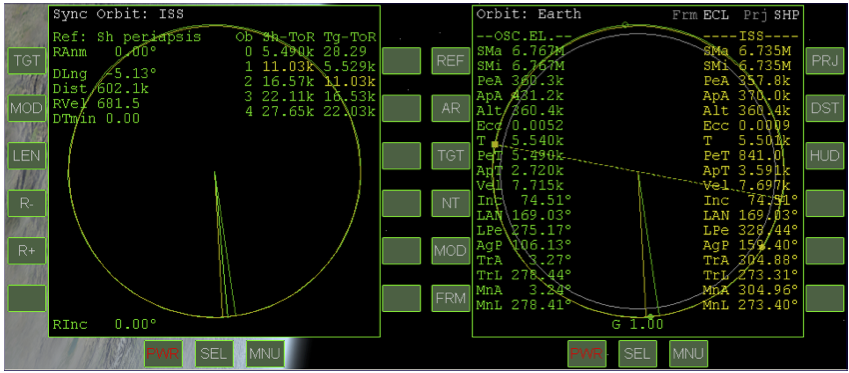
- The adjustment in this case is quite small (DTMin in the recording was only about 13 seconds), so be sure you are in translation (LIN) RCS mode, and use only forward/backward (KEYPAD-6/9) linear thrusters to adjust PeA to drive DTMin as close to zero as possible. Again turn off prograde to save fuel. Take a look at the MFD’s below, just after DTMin adjustment for the recorded flight. Note that DTMin is 0.00 as expected, and that the ship time on reference point (Sh-ToR) value is 11.03k seconds, or just about two orbital periods away (T = 5.540k).
- Carefully accelerate time (10-1000x) until the top line of the Sync MFD is yellow.
- This will be about two orbits. The yellow line represents the orbit where the target will be closest among those listed. Recall that Sh-ToR is your time to the reference line, so when you get to about 900 for this value (15 minutes from intercept), go to 1x time and prepare for docking. On the final two orbits, the green and yellow radius vectors will converge, and the angular difference DLng will get smaller, as will the distance (Dist) and relative velocity (RVel). You will also be happy to see the sun rising around 600 seconds before intercept, so you can dock in daylight.
Docking
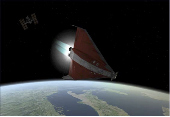
It’s important to pay attention in space! In the recorded flight, I think I got a bit carried away with the scenery or something, because as I reached 190 seconds Sh-ToR (3 minutes to intercept!), I was over the coast of England waving hello to Dr. Schweiger in London instead of thinking about slowing my approach to the ISS which was only 3.5 km away and closing at about 18 m/s. Actually I wanted to end up stabilized (zero relative velocity) about 1 km from the ISS to avoid an overly long approach, but I started my tail-first approach burn late (as above, looking at Italy) and I ended up stopping at 800 m instead. A bit close, but it worked out OK. Here are the steps to follow, with suggestions for a bit more safety margin. Note that not all Sync MFD approaches work out quite this precisely, and your nearest approach to the target may be several kilometers. The Docking HUD and Docking MFD can still work in such cases (see Smitty’s Orbital Operations Tutorial for more general instructions).
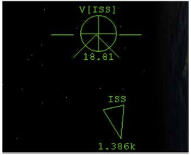
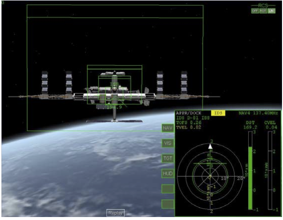
- 'At around 5 km from the ISS, rotate your nose to the V[ISS] symbol as shown.
If you are pointed at the ISS as you close in the last few minutes, you will see the –V[ISS] (plus sign) symbol which indicates the direction of your closing velocity. The V[ISS] is 180° from this direction and therefore “behind” you, so you will need to rotate (pitch or yaw) and point your tail at the ISS. Pointing at the V[ISS] HUD symbol and thrusting forward will reduce the relative (closing) velocity, the value of which is displayed under the symbol (18.81 m/s here). Note that when the target is off-screen, an arrow shows its direction and distance (1.386 km in this case).
- At around 2 km, start to thrust toward the V[ISS] symbol.
- You could start sooner and use linear RCS thrusters, but a couple of careful main engine pulses will kill most of the relative velocity in this case. In other docking situations, you may have a larger closing velocity and may need to be more aggressive with the main engines. You can thenuse linear thrusters (forward/back) to reduce it further. The goal is to get very close to zero (0.01- 0.03 is OK) at about 1 km distance from this ISS. Note that as you get closer, the direction will change, and you may need to switch back to rotation to re-point the nose at the velocity indicator before applying further linear forward/back thrust to zero it out (shown in the recording).
- Rotate to put the nose on the ISS, then set up for docking as follows.
- If you are only a kilometer or so from the ISS with zero RVel, the Sync MFD has done its job and you can power it down to give better visibility for docking (assuming you are using the no-panel view). But if you have Orbiter Sound installed, you may be hearing an annoying beep now – the radar proximity warning. You can turn it off before closing the left MFD.
- 1. On the left MFD, click [SEL], [Radio/MP3 panel], [RAD], and [PWR] (off).
- 2. On the right MFD, click [SEL], [Docking], [NAV] (three times), then [HUD].
- This will set up the docking MFD to use NAV4 which has been set to 137.40 MHz, the IDS (instrument docking system) frequency for ISS docking port D-01. The ISS in Orbiter has five docking ports – you can find this and other detailed information in the CTRL-I (info) dialog box. Why port D-01? It worked out OK in the recording, although it was not pointing in my approach direction. Feel free to try out other ports and see if they seem easier to approach (you can cycle through the four defined frequencies with [NAV] and send the port info to the HUD with the [HUD] button).
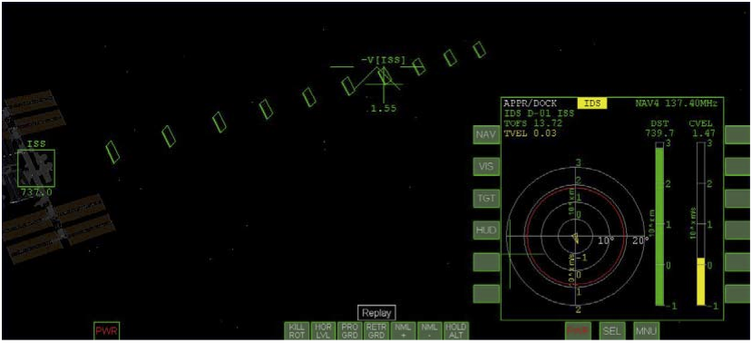
- Use lateral LIN (left/right, up/down) thrusters to move the –V[ISS] symbol onto the outer docking boxes as shown below.
- The docking boxes are like a “road in the sky” leading to the selected docking port. If you just head directly for the ISS, it will be hard to get lined up with the docking port. The docking boxes are like an ILS glide path for a runway (if you are familiar with instrument approaches!).
- Use forward RCS thrust to start closing on the boxes.
- Here’s where you need some patience (or some 10x warp), since 740 m at 1.5 m/s will take 8 minutes to cover. This is nothing in real world docking (the Space Shuttle takes days to rendezvous with the ISS, hours for the final few hundred meters and docking), but you can get tired of waiting. You can stay fairly slow and use 10x time acceleration, or you can try some small bursts of main and retro engines (better open the retro doors to be ready, Control-Space).
- When you get near one of the outer docking boxes, switch to rotation and turn and face the ISS.
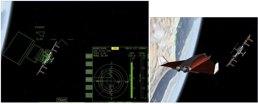
- Recall that KEYPAD-/ toggles between LIN and ROT (or you can use the screen buttons in the upper left corner of the no-panel view). You may not really be “inside” a box at first – you may be above or below or otherwise offset from it. You will probably need more lateral translation as well as rotation to get into position to “slide down” the docking boxes, and you may pass the ISS at some point and see your closing velocity (CVEL) go from positive to negative – this is OK since you are going to one of the outer docking boxes to get lined up before trying to close the range for docking (you could also get lucky sometimes and pick a docking port whose IDS boxes point right toward you, saving you a lot of maneuvering). Don’t worry about perfect alignment or position now – just pointing at the ISS with the docking boxes somewhere in front of you is OK for starters (as in the example below).
- This maneuvering can be confusing at first. Feel free to use the outside view to get a better feel for the 3D geometry of your approach. You won’t see the docking boxes, but by spinning your view with the right mouse button, you may be able to better visualize the situation.
- If your closing velocity (CVEL) is positive, use forward or backward LIN thrust (KEYPAD-6/9) to drive it close to zero.
- CVEL of around 0.02 or 0.04 is OK – you just don’t want to close the range much more until you can really get the IDS boxes in front of you, and start to get aligned rotationally (this is the X symbol shown in red in the Docking MFD above), and somewhat aligned laterally (that’s the green plus sign). Just having the X and the + appear on the MFD is good enough for now.
- Use lateral (left/right/up/down) LIN thrusting to put the –V[ISS] HUD symbol inside one of the outer boxes and thrust toward it.
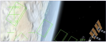
- Remember that this symbol shows where you are heading relative to the ISS. It’s OK to have a positive CVEL if it’s taking you into one of the boxes (the picture is intentionally cropped to show mainly the boxes, showing only part of the ISS itself).
- When you get nearly inside one of the boxes, switch to ROT and use pitch, yaw, and roll to point at the ISS and get lined up with the boxes (double-line at top).
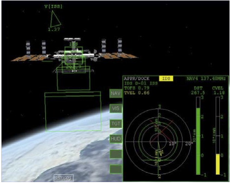
- Once you get in the “right” orientation things will seem a lot less confusing and you can begin to mentally separate your problems as rotational (pointing, shown by the MFD X) and lateral alignment (shown by the MFD + sign). Rotation should be solved first, even if you feel you are too high or too low as a result. Closing a bit fast in this view (1.18 m/s), need to slow down.
- Use linear RCS thrusters to slow CVEL to nearly zero again.
- You need to stabilize several hundred meters away to complete your alignment with the HUD boxes and get ready to fine tune the alignment with the Docking MFD.
- Use rotational RCS thrusters to get the Docking MFD X symbol lined up with the center of the rings (angular alignment).
- Rotate toward the X – if it’s above the center in the MFD, pitch the nose up (KEYPAD-2), if it’s to the left, yaw left (use Kill Rotation as needed). It can be a little off now, but get it mostly lined up (the X will turn white). This will make your nose-tail axis parallel with a line sticking straight out of the docking port. With this solved, you will know that any deviation you see is due to lateral shifts and not due to looking from a skewed direction.
- With angular alignment solved, use linear thrusters to line up the MFD “plus sign” with the center of the rings for lateral alignment.
- Thrust toward the MFD cross to move it – think of this as the target, and if the target is to the left, you thrust to the left. You will also notice an arrow that appears on the MFD to show the direction and magnitude of your lateral motion. This will usually take a number of tries and constant adjustment until you get a feel for it. You may also find that the angular alignment drifts a little – if so, switch to ROT and correct it, using fine thrusters (CTRL-KEYPAD) if necessary to really center it (it should stay centered pretty well on its own unless you have gravity gradient torque and/or nonspherical gravity sources checked in the Launchpad Parameters page – these settings are more realistic but can make docking a bit more challenging). Don’t forget to switch back to translation (LIN) RCS mode.
- When angular and lateral alignment are both good and relatively stable, use LIN forward thrust (KEYPAD-6, not main engines) to start to close on the port.
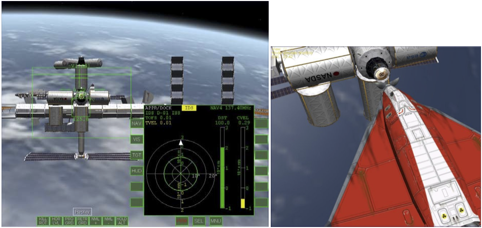
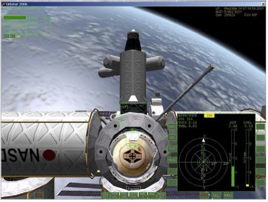
- You can close at 0.3-0.5 m/s or so, slow enough to make corrections but fast enough to see progress. When you get within 5 m or so, you should slow to about 0.10 m/s for final docking. When you are stable, you will find that the -V[ISS] cross will sit just a bit higher than the docking port (because the DG’s docking port in the nose is lower than your eye point). The key point is “when you are stable” because if there is any lateral velocity, the cross will drift. Use both the outside view and the Docking MFD to keep track of what’s happening and try to keep everything “happy.” Unless the MFD X gets off-center, use only LIN thrusters from now on – no rotations.
- Open the nosecone with K to expose the docking port (if you ever closed it).
- In the recorded flight, I never did close it. Bad form! Check the outside view to be sure whether it’s open or closed (there is no nose cone position indicator on the no-panel cockpit view).
- Slow to around CVEL 0.1 m/s to close and dock.
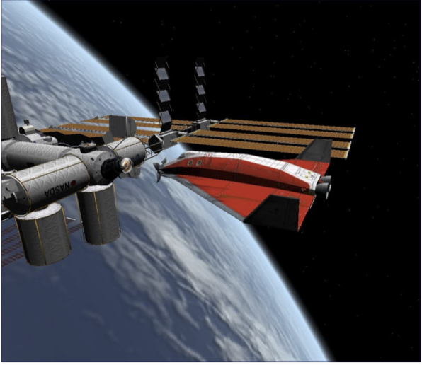
- If you get substantially out of alignment when within DST 75 m or closer, it’s best to back up to 100 m or so, reduce separation rate to near zero, and fix your line-up, then start to move in again. It’s quite hard to fix a bad alignment when you are very close – as with a good landing in an airplane, the secret of good docking is a good approach. Congratulations on docking!
Summary of Steps (Dancing in the Dark)
These summary steps are relatively brief, so refer to the main text and/or pictures if any points are not clear. This is mainly to prompt you in the steps once you are familiar with the procedure. Note that this is not the only way to do rendezvous and docking, but this is a good start.
Setup
Follow the steps on page 5-3 through 5-6 to set up the starting point with the Scenario Editor
- OR
Skip the setup by starting with the playback scenario DG-ISS Sync-Dock.scn located in the Scenarios/Tutorials folder, using CTRL-F5 to interrupt the playback whenever you wish to start doing the following steps yourself.
Rendezvous/Sync
1. Carefully accelerate time (10-1000x) until the ISS is approaching your periapsis, then slow to 1x.
2. When the ISS reaches your periapsis, pause or slow to 0.1x and write down the Alt (altitude) value of the ISS there (On Orbit MFD, the ISS altitude when yellow line aligns with solid green dot).
3. Accelerate time again until your ship is close to apoapsis (e.g., ApT ~60), go to 1x, and turn prograde.
4. When you reach apoapsis, apply several short bursts of main thrust to raise your periapsis (PeA) to exactly match the ISS altitude you wrote down (use linear 6/9 thrusters to fine tune the value).
5. Accelerate time again until your ship is close to periapsis (e.g., PeT ~60), go to 1x, and turn prograde.
6. When you reach periapsis, watch the DTMin value (minimum time separation at reference point, which is your ship’s periapsis in this case) in the Sync MFD, and use forward/backward linear thrusters to adjust DTMin to zero.
7. Carefully accelerate time (10-1000x) until the top line (orbit0) of the Sync MFD is yellow. Slow to 1x time and prepare to slow down for docking (pause or slow to 0.1x while you read docking steps).
Docking
8. At around 5km from the ISS, rotate your nose direction symbol to point directly at the V[ISS] symbol (circle with plus sign). This will be behind your ship, so your engines will be pointing at the ISS.
9. At around 2 km, start to thrust toward the V[ISS] symbol (short bursts of main engines) until V[ISS] is close to zero (0 to 0.02). Use linear thrusters to fine tune so you are not closing significantly with the ISS, but “hovering” about 1 km away.
10. Rotate to put the nose on the ISS, then set up for docking as follows (1) Power off the left MFD (2) Display the Docking MFD on the right with [SEL] and [Docking]. Click [NAV] three times then [HUD]. You should see the HUD docking boxes leading to port D-01.
11. Use lateral LIN (left/right, up/down) RCS thrusters to move the –V[ISS] HUD symbol onto the outer docking boxes.
12. Use forward RCS (linear) thrust to start closing on the boxes.
13. When you get near one of the outer docking boxes, switch to rotation RCS and turn and face the ISS.
14. If your closing velocity (CVEL) is positive, use forward or backward LIN thrust (keypad 6/9) to drive it close to zero.
15. Use lateral (left/right/up/down) LIN thrusting to put the –V[ISS] HUD symbol inside one of the outer boxes and thrust toward it.
16. When you get nearly inside one of the boxes, switch to ROT and use pitch, yaw, and roll to point at the ISS and get lined up with the boxes (double-line at top).
17. Use linear RCS thrusters to slow CVEL to nearly zero again.
18. Use rotational RCS thrusters to get the Docking MFD X symbol (which may not be visible if you are badly misaligned with the port) lined up with the center of the rings (angular alignment, it will turn from red to white when lined up). Rotate toward the X in the MFD to center it.
19. With angular alignment solved, use linear thrusters to line up the MFD “plus sign” with the center of the rings for lateral alignment. Thrust toward the MFD cross (+) to center it.
20. When angular and lateral alignment are both good and relatively stable, use LIN forward thrust (keypad-6, not main engines) to start to close on the port.
21. Open the nose cone (if closed) with K to expose the docking port.
22. Slow down to around CVEL 0.1 m/s to finally close and dock.
| Chapter 4: Fly Me To The Moon | GPIS Contents | Chapter 6: Reentry |
