IMFD Background
| IMFD Manual Contents | IMFD Manual Contents | IMFD Configuration Page |
Interplanetary MFD Background Information
Interplanetary MFD is one of the two powerful navigation tools in Orbiter (the other one being TransX MFD). IMFD is a flight navigation computer designed to accomplish almost any navigation feat that you might want to achieve.
Start Key Selection
You can define the key that is used to open this MFD. The IMFDKey variable can be edited in the IMFD.cfg file. Key codes are listed in an orbitersdk.h and the default setting is "I".
Color configuration
IMFD allows colors to be configured by configuration file. The file is located in Config folder and the file is named IMFD.cfg. The same file will be used at least by BaseSyncMFD.
Setting values from keyboard
You can set up values in a many forms from the keyboard by pressing the [Set] button. The exponent form can be used. Examples are ―12.4e3‖ or ―11.45e-2.‖ Also the exponent can be replaced by a letter like ‖12.4k‖ or ‖33.2M‖ or ‖22.2G‖ where k is equal to ―e3‖ and so on. ―d‖=day and it will multiply the input value by 86400. ―h‖ is equal to an hour, and ―a‖ is one astronomical unit.
Sharing Flight Plans
A Single flight plan can be "shared" between multiple MFDs by setting IMFD into remote access mode by pressing [PG] button in the main menu. A popup window will ask for an ID code of the MFD being accessed. The ID code of an MFD is shown in the top right corner of the MFD. The flight plan will stay in the MFD it is planned in even if the MFD containing the flight plan is closed so the other MFDs can access the plan. If you want to disconnect one MFD from another just input an invalid ID, which could be the ID of the MFD itself or just a random number that is not an ID of an open IMFD. When using two IMFD‘s they cannot access each other. For example, when using two MFD‘s, only one of them can use remote access to access data from the other.
3D Rotation
Some of the programs support 3D rotation via mouse. Hold down shift and spacebar OR shift and the Z and L keys to rotate the display. Currently supported programs are: Target Intercept, Planet Approach. Only the Left and Right MFD displays can be rotated. To get the display back to normal, hit the PRJ button on the MFD you just rotated.
Time in GET and UT
It is possible to enter dates in UT format like ―UT 14-nov-1969‖ or with the 24h clock ―UT 14-nov-1969 17:45:21.1‖ Used names for the months are Jan, Feb, Mar, Apr, May, Jun, Jul, Aug, Sep, Oct, Nov and Dec (not case sensitive). IMFD 5.0 supports GET (Ground Elapsed Time). This feature can be activated from the configuration page. Also the date of launch must be specified. You can enter data in GET format by pressing the [Set] button and entering the time ―GET 120:34:56.7‖. When flying with AMSO IMFD will receive GET time via the inter-process-com link.
What is EIn?
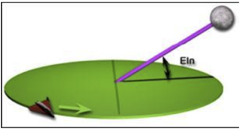
In IMFD EIn is used to express angle between the current velocity vector and the vector of the target‘s orbital plane. However, it is not the same as relative inclination between orbital planes. Typical situations are: How much the escape vector is out of the source plane, how much the target is out of the source plane, and how much the vessel is out of the target plane. In other words it presents an alignment or a launch window. Basically, EIn is to interplanetary flights as RIn is to Lunar/Space station flights.
EIn, Orientation of the lunar orbit doesn‘t matter here
What is RIn?
RIn is a relative inclination it used to display the angle between orbital planes. The target plane is always one of these planes. And the other one is either the source plane (green) or the plane of the hypothetical transfer orbit (purple). In many situations it presents the magnitude of the plane change in degrees.
Information Flow
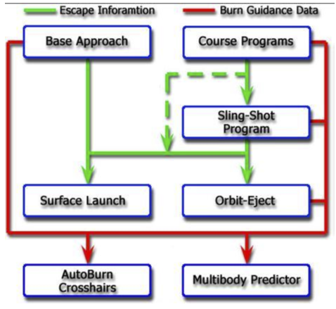
IMFD contains separate programs for transfer, slingshot, orbit-eject, trajectory plotting, and burn control. There is some information transferred form one program to another, beginning with the transfer programs and ending in the trajectory plotting and burn control.
Information Flow in IMFD
LambertAP Mode
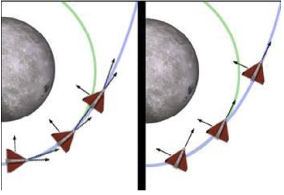
This option specifies the primary operation mode of the guidance system of the IMFD. There are two options available—"IMFD" and "ApolloP30". The setting will affect the reference frame of the Burn Vector view, powered flight attitude control, behavior of the Autoburn, and trajectory prediction of the map program. In IMFD powered flight, steering uses constant pitch and yaw angles respect to velocity vector of the vessel. Delta velocity is displayed relative to the velocity vector in the thrust monitor. The ApolloP30 is the AGC P30 compatibility mode that uses a constant attitude in the global frame during burn. Delta velocity is displayed in a compensated local vertical system as P30 input requires. Autoburn tries to operate as P30/40 does. Basically, just leave the mode in IMFD mode; it will get you where you want to go.
Fixed attitude and velocity relative attitude
Sources, Targets and References
For correct operation of the transfer program, the source, reference and target must be correctly defined. The reference and source objects are automatically set after setting the target. So, start the flight plans by setting the target first. If necessary the reference and source can be manually overridden. If for some reason the source of the target is incorrectly defined an error will be displayed. To be able to generate an escape vector the source must be set to the planet being orbited (planet you start at). By setting the source to ―x‖, the current ship will be selected. When using IMFD the target must be always defined, otherwise the ecliptic is targeted automatically. There are some special targets available—see the Map program section for more details. Space stations can be targeted and sometimes they can be used as a reference objects but a space station cannot be a source object. Target [TGT] and reference [REF] selection buttons are in a left edge of the MFD and the source [Src] button is in a second button page in a right edge. Change the page with [PG] button. A list of Reference, Target, and Source settings for various flights is available in Appendix C.
Burn Guidance
Most of the programs are capable of generating burn data. The data will appear in the lower left corner and there is a Time to Burn (TtB) item and remaining Burn Time (BT) item. After the (BT) there might be (PG) or (RG) flags. Those will indicate that the burn is a pro-grade (PG) or a retro-grade (RG). If the flag is not present the burn will use a burn vector and you must use a cross hair tool to setup the attitude of the space craft. The cross hairs will appear when pressing [BV] button. Also the autoburn will complete the burn automatically, so there is no need to play with the cross hairs unless Autoburn acts crazy, which is not likely. The autoburn can be activated and deactivated by pressing [AB] button. When using spacecrafts that rotate slowly you may want to decrease an attitude control speed from IMFD.cfg, which would be AP MAX ANG VEL which is the maximum angular velocity when Autoburn controls your attitude (rad/sec).
Burn Integrations
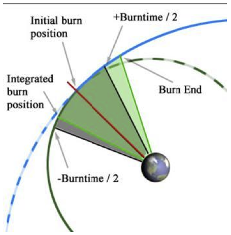
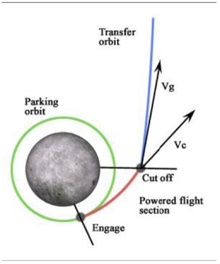
In IMFD burn integrations are used to improve the accuracy of the burns. Typically in a transfer calculation, it is expected that the delta velocity is gained at once with no burn time at all. This is the initial burn executed in the initial position. However, in reality, the time of the burn must be taken into account somehow. The easiest way is to reduce half of the estimated burn time from the initial burn position. Thus, that would be the actual position where the engines should be started. The ship will end up, almost but not exactly, in the right direction. The grey sector in the picture below shows this method. In the burn integrations, numerical methods are used to calculate the burn position more accurately, so that the ship ends up in a trajectory that matches the initial target trajectory as well as possible. This technique is used with the Pro- and Retro-grade burns. The green sector displays this technique in the picture below.
Idea of burn integrations
Burn Timing
If for some reason above integration fails, the burn position will start jumping all over the place. Due to the experimental nature of this method it is possible to control it from the IMFD Menu by pressing [PRJ] button. If this happens in Base Approach, try changing the Num value.
Burn Guidance Modes
Prograde Guidance Mode
This will definitely fix the problems with long burns in low earth orbits. This method OR Off-Axis Mode is a good choice in many long burn situations. The idea of this method is to adjust the burn position and burn time so that the velocity to be gained will be equal to the velocity of the vessel at engine cut-off.
Prograde burn mode
Realtime Guidance Mode
Realtime mode is designed for short duration course correction maneuvers. The maneuver can be considered to be short when the traveled central angle (the Reference Planet being the vertex) during the burn is very small. Realtime mode is improper in long duration low orbit maneuvers like the TLI burn, although it can be used with no problems. In this mode, the software computes the target velocity vector in realtime and the vector changes its magnitude and direction while the vessel moves forward. This mode is recommended for any type of mid-course corrections.
Off-Axis Guidance Mode
Off-Axis mode is specially designed for the Apollo TLI burn. This mode applies some thrust for all 3 axes and can be used even if the orbits are not perfectly aligned. This mode will compute a numerical solution to place the vessel in target trajectory. This mode requires that the time to ejection (TEj) is higher than 3 seconds. Below the 3 seconds the program no longer generates new information for the burn execution programs (Autoburn / Thrust Monitor Program) as during this time they are preparing to execute the burn. This mode is recommended for long duration low orbit maneuvers like TLI, TEI, Orbit Insertions and Orbit Ejections.
Burn Vector View
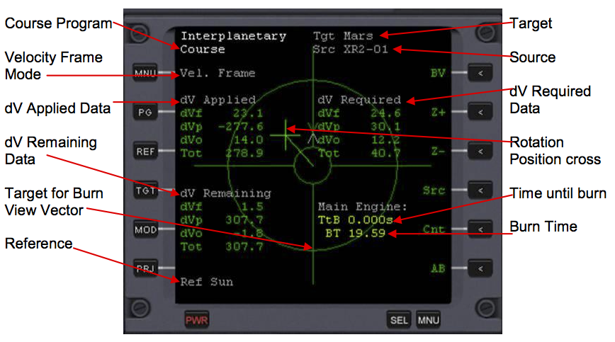
Burn Vector View displays more detailed information about a burn. The contents of this display depend on the guidance mode (realtime, off-axis or prograde). When using realtime mode, only applied and remaining delta velocity are displayed. Remaining delta velocity is computed by flight software in realtime. In other modes the delta velocity is numerically computed and predefined for the burn. You can select the reference frame used in burn vector view from the configuration page. You really do not need to worry about the technical information that follows, but know that the most important thing is Tot (Total dV) under dV remaining. This is the total amount of dV in meters/second left in the burn.
dV Applied
This section displays the delta velocity that is sensed by onboard equipment. It is integrated from the thrust generated by thrusters over time. dV Applied can be reset by switching the Autoburn [AB] on and off.
dV Required
This section displays required total delta velocity. This section is displayed only if exact values are known, not in a realtime mode. The numerically integrated accelerations over time is given by ![]()
dV Remaining
This section displays the remaining delta velocity. It is total delta velocity minus applied delta velocity. This is the most important display—it shows how much more Delta Velocity you must burn.
Local Vertical
Defines a reference system where the z-axis (dVo) points away from the planet. ![]()
The y-axis (dVp) points direction of orbit normal. The x-axis, or (dVf), points to the horizontal direction of flight. ![]()
Local Velocity Frame
Defines a reference system where x-axis (dVf) is pointing prograde direction. ![]()
Y-axis (dVp) points in the direction of orbit normal and z-axis (dVo) points outbound direction. ![]()
Burn Vector View:
The cross represents your rotation position. Rotate your vessel towards the cross. When the cross turns grey, you are rotated to the correct attitude and you can start your burn (if you want to do it manually). Autoburn will automatically rotate you and automatically perform the burn for you. In dV Applied, dV remaining, and dV Required, dVf is the x-axis, dVp is the y-axis, and dVo is the z-axis, and Tot is the total delta velocity.
| IMFD Manual Contents | IMFD Manual Contents | IMFD Configuration Page |
